Using the THAT1646 As A Transistor Pre-Driver/Headphone Amp

Where we discuss new analog design ideas for Pro Audio and modern spins on vintage ones.
Post Reply
User avatar
mediatechnology
Posts: 5437
Joined: Sat Aug 11, 2007 2:34 pm
Location: Oak Cliff, Texas
Contact:

Using the THAT1646 As A Transistor Pre-Driver/Headphone Amp

Post by mediatechnology »

As many of you know I've explored unconventional ways to use the THAT1646.

See: https://www.proaudiodesignforum.com/for ... ?f=6&t=140

We've discussed driving the THAT1646 in common mode so that both outputs swing together rather than anti-polarity. In the common mode configuration I've explored thus far, the differential input is grounded. Both 1646 outputs, or multiple 1646 outputs may be paralleled this way to increase drive current.

What if more drive current is needed? One application would be a headphone amplifier, where the combined outputs are not quite enough to drive 32 ohm headphones to ear-splitting level.

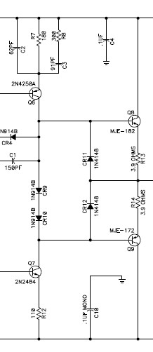
External boost transistors and the 1646 could be used together to increase drive. In conventional applications one often sees a two or three diode bias string to provide transistor bias. The 1646 however has a differential input that produces an output gain of two. That input is used here to provide bias and Vbe multiplication.

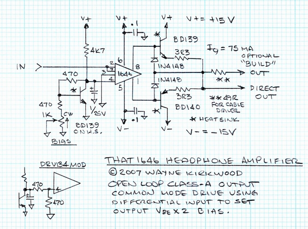
Here's an open loop test circuit I developed:

Image
Drawing Editied 8/19/07 18:04 CDT

This is the current schematic:

Image
Discussion:

Common mode drive is applied to pins 2 and 7 of the THAT1646. As a result both outputs "yen and yang" together rather than in anti-polarity. The outputs from the THAT1646 are taken into the bases of the external boost transistors, an MJE243 MJE253 complementary pair. The THAT1646 outputs are capable of 50-75 mA drive.

To establish a 2 Vbe bias at the output transistor's bases a bias reference of 1 Vbe is injected into the "differential" input, pin 4. This 1 Vbe reference gets multiplied to 2 Vbe by virtue of the x2 differential gain of the 1646. If required, the reference diode can be thermally coupled to one of the output devices. In the test circuit, the standing current was measured to be approximately 20 mA.

Emitter degeneration resistors of 3R3 are used. The test load was 30 ohms representing the low impedance range of many headphones. At this power level, the external transistors should be heatsinked with the reference diode thermally coupled to the devices.

This is not an optimized design but a proof-of-concept and it works rather well. Remember that the output buffers are running open loop.

With 18V supplies the circuit will effortlessly drive 30 ohms to more than 20 V P-P. This is about 2 watts or +33 dBm.

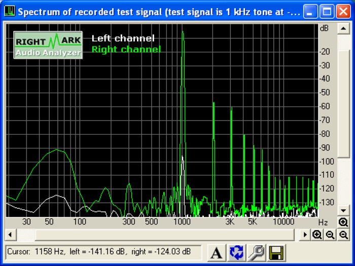
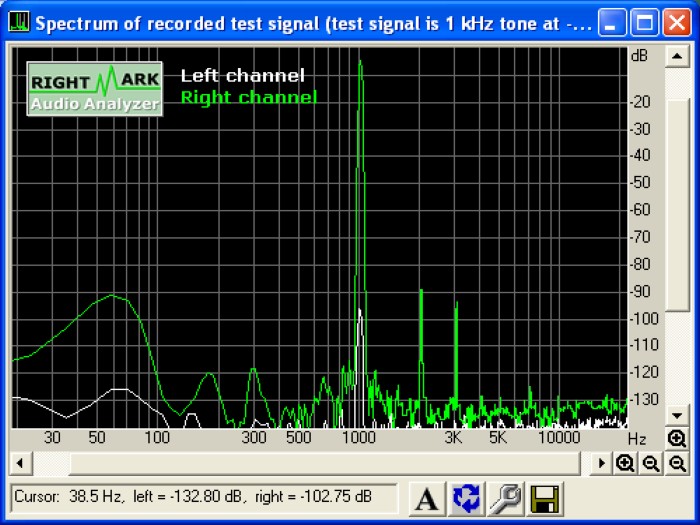
Distortion performance, measured only at 1 KHz for now, is about -70 dB 2nd and -70 dB third open loop. With a "helper op amp" wrapped around the buffer to provide negative feedback performance is expected to be even better.

With a darlington configuration and a 2 Vbe reference it is conceivable that a modest power amp could be made using this relatively simple pre-driver made from a THAT1646.
User avatar
mediatechnology
Posts: 5437
Joined: Sat Aug 11, 2007 2:34 pm
Location: Oak Cliff, Texas
Contact:

Re: Using the THAT1646 As A Power Transistor Pre-Driver

Post by mediatechnology »

Thanks Roger.

No I didn't see much offset which is surprising. Maybe I got lucky "matching" random transistors.

For a line driver you can't beat the bare 1646 or a 1646/transformer configuration as you've shown us.

The open loop distortion performance driving 30 ohms is not spectacular: I suspect that a darlington configuration would be better as well as operating it closed loop. It's also easy to forget that the THAT1646 has 25R x 2 output Rs per leg so the additional current gain couldn't hurt. I wanted to try a difficult load first.

As a headphone amplifier with a 27 ohm build out (from PRR at Prodigy) it is a little less "strained" distortion wise typically -80 dB at both second and third at 10V P-P.

It needs a lot of work but I thought it was kind of a unique way to use the 1646. It might actually make a pretty decent headphone amp. I also want to see if I can make a simple low power amp for a spring reverb driver.
User avatar
mediatechnology
Posts: 5437
Joined: Sat Aug 11, 2007 2:34 pm
Location: Oak Cliff, Texas
Contact:

Re: Using the THAT1646 As A Power Transistor Pre-Driver

Post by mediatechnology »

I lowered the pullup resistor to the bias diode to 1K. With a 68 ohm load I now see 1 KHz open loop distortion figures of -100 dB at 2nd and 3rd at 10V P-P. The Iq is roughly 80 mA.

I'm thinking that 68 ohms is a realistic load for 32 ohm headphones with a 27R buildout.
User avatar
mediatechnology
Posts: 5437
Joined: Sat Aug 11, 2007 2:34 pm
Location: Oak Cliff, Texas
Contact:

Re: Using the THAT1646 As A Power Transistor Pre-Driver

Post by mediatechnology »

I just thought about the offset and why we're not seeing it.

In a conventional output, lets use a 990 as an example, we have a bias string that looks like this:

Image

CR9 and CR10 set the Vbe delta for the output devices. But the anode cathode voltages are established by the currents flowing in Q6 and Q7. Various offsets prior to Q6 and Q7 can affect the output offset in addition to Vbe mismatch in the output devices. So the 2 Vbe window can slide up and down relative to ground.

With a THAT1646 driving the output transistors the 1646 output offset is quite low relative to ground. The primary offset would seem to be Vbe mismatch between the output devices. I may be wrong, but I think Vos will be acceptable for this circuit without a servo.

EDIT: Yep there's a real difference between the two: With the 1646 the 2 Vbe will be mirrored essentially equally above and below ground. In the 990, for example, the 2 Vbe window slides. In terms of output Vos this works to our advantage.

On the test circuit I'm measuring an open loop Vos of about -6 mV at the load.

One other thing that came to mind: I measured the 2Vbe (base-base) and it was slightly less than the diode "Vbe." Then I remembered that the 1646 is gain accurate with 10K bridging loads.* Our power amp stage prevents a significantly lower load. Given that, increasing the Vbe at the reference is probably a good idea and thus the improved distortion performance with a 1K pull-up versus the original 10K. It's fun to pull the Vbe bias completely and see the amp exhibit a classic Class B waveform with a zero crossing dead band. We could also use a 1.85V** LED and divide it by two resistively for full Class A.

* The THAT1646 and SSM2142 have slight gain differences. The 2142 is gain-accurate for 600 ohm loads, a value not often seen in modern practice. The 1646 is optimized for 10K loads.

** A 1.85V Vf LED will emit at ~640 nM. I think this is the "original" red chemistry chosen for its' 3500 ppm tempco. We can use any Vf as long as we divide it and it tracks well. The main thing is getting it thermally connected to the transistor. Having a small one and sticking it in the device's mounting hole is kind of handy.
User avatar
mediatechnology
Posts: 5437
Joined: Sat Aug 11, 2007 2:34 pm
Location: Oak Cliff, Texas
Contact:

Re: Using the THAT1646 As A Power Transistor Pre-Driver

Post by mediatechnology »

I just rebuilt this little circuit on it's own protoboard with a better heatsink.

The idle current as measured through the V+ lead is 60 mA. So with 36 V supplies this little baby is burning off 2.2 watts Class-A while it's doing nothin'.

Image

Nah - Don't think I'll go for the rating.

I did measure the slew rate at ~5V/uS. Not bad for driving phones I suppose. Sure beats an LM386.

IIRC the 1646 in Vcm drive was about 7.5 V/uS.
SSLtech

Re: Using the THAT1646 As A Power Transistor Pre-Driver

Post by SSLtech »

Hey, that's inspired thinking!!!

darnit, if I wasn't already sourcing parts for a stereo pico build, I'd be trying this out right now... perhaps this could be a handy little headphone 'monitor' out on the pico! ;)

Keef
User avatar
mediatechnology
Posts: 5437
Joined: Sat Aug 11, 2007 2:34 pm
Location: Oak Cliff, Texas
Contact:

Re: Using the THAT1646 As A Power Transistor Pre-Driver

Post by mediatechnology »

Thanks Keith. I want to find a way to operate it closed loop with a "helper" op amp next.

But with the distortion so low as it is (with the final buffer operating Class-A without global or local feedback) I'm tempted to just quit and leave it alone.

For a portable version (stereo would pull 120 mA min) hook it up to not one, but two cars with jumper cables. Two cars are required because it's operated from bipolar rails...

BTW Thanks for joining us here!

You may want to check over in the announcements and make sure topic reply/subscriptions are configured for you.
Sender
Posts: 3
Joined: Tue Aug 14, 2007 3:02 pm

Re: Using the THAT1646 As A Power Transistor Pre-Driver

Post by Sender »

Sorry for the slightly off topic question, but it does pertain to the 1646.

I was thinking about implementing the 1646 into a non-balanced project (The FETBoy, perhaps you're familiar with it). What is the maximum amount of input signal the IC can take before distorting?
User avatar
mediatechnology
Posts: 5437
Joined: Sat Aug 11, 2007 2:34 pm
Location: Oak Cliff, Texas
Contact:

Re: Using the THAT1646 As A Power Transistor Pre-Driver

Post by mediatechnology »

sender:

I haven't actually tested the maximum input range and it does depend on supply voltage. A very good question.

I'm assuming that you're going to be using the unbalanced "common-mode" drive using the paralleled sense +/- pins as input and taking the output from both pins 1 and 8 in parallel.

What I can tell you is that the output level clips at typically Vcc - 2.2V and Vee +2.25. Since the part used differentially has 6 dB of gain, it is possible that the input range could be far less. But I think not.

From measurement in a single-ended (Vcm drive) configuration however I think the clipping point is limited by the output, not the input. I was able to easily obtain output levels of 20V into 100R. Now that's only 10V peak with 18V rails: The voltage was limited by load current. The 1646 unloaded had lots more swing available I just don't know how much.

Used with differential drive and with a gain of 6 dB the output would definitely be the limiting factor.

One thing I should always point out about the THAT1646 as well as the SSM2142 and DRV134 is that if it's being used single-ended (in a conventional configuration) the unused output must be grounded. Otherwise all of them will be noiseier than they should be.

When I get my THAT1646 headphone amp fired up I'll measure it for you.
User avatar
mediatechnology
Posts: 5437
Joined: Sat Aug 11, 2007 2:34 pm
Location: Oak Cliff, Texas
Contact:

Re: Using the THAT1646 As A Power Transistor Pre-Driver

Post by mediatechnology »

I've been mulling over the use of a "helper" op amp to provide output stage linearity compensation and reduce class-A idle current.

I decided to see what the addition of a 5534 would do in order to get global feedback into the THAT1646 input. Using the Jim Williams (of Linear Technology Corp, not Audio Upgrades) "Op Amp Booster" series as a reference it became obvious that an inverting stage was the only way to go. Since the 5534 has higher bandwidth than the THAT1646/driver transistor combo driven in the unique common mode configuration it needs to be slowed considerably. As Williams points out, if the input device bandwidth exceeds the output stage it will oscillate. So I used both a 47 pF Cc and a local, to the 5534, Cfb of 33 pF. These were empirically determined to provide the best stability. Rin and Rfb were chosen to be 10K. It provides a pretty decent square wave response and will drive a 0.1 uF cap at the Re junction and still maintain stability. I would post the drawing but as we shall see it may not be necessary. The distortion figures speak volumes.

This is the generator output:

Image


This following is with a 5534 helper op amp. As mentioned above the 5534 has both a 10K Rfb and Rin. Cc is 47 pF. There is also a 33 pF Cfb locally around the 5534.

Iq is 30 mA. Rbuildout is 22 ohms. Rl is 47 ohms. Note the 4th and 5th harmonics. The distortion is consistent regardless of Rl. The output of the 5534 was observed to have increased THD levels at its' output indicating the correction it is applying.

Image


The following is without the 5534 helper op amp at an Iq (circuit total not class-A current) of 30 mA. The distortion performance is horrible. So the 5534 is doing something. Rl is 47 ohms.

Image


This is the open loop performance without a helper op amp at a 75 mA Iq. Not the absence of higher-order harmonics and the dominant 2nd harmonic at ~-85 dB. Rl is 47 ohms.


Image

This is also at 75 mA Iq without Rl.


Image

Conclusion

The only motivation for adding global feedback was improved linearity performance at lower idle currents. The DC performance, including offset, are excellent without NFB thanks to the Mirror Bias (tm) arrangement formed by the THAT1646. If it were my preamp (and it is) I think I would rather burn off an extra 45 mA/Channel for the lower distortion open loop performance than use a helper op amp, with increased distortion, in order to save the current.

As JohnR says: "YMMV."
Post Reply