An Improved Servo for the THAT1510 and THAT1512
Posted: Tue Apr 14, 2009 1:04 pm
I see a lot of questions here and elsewhere asking about servos for the THAT1510 and THAT1512. This post will discuss an improved servo circuit which has the goals of reducing switching clicks during gain change and eliminating a large value Cgain. An added benefit of this circuit is that output offset is significantly reduced.
Without a large value (3300 uF typ) series capacitor in the Rgain line, the THAT1510 or 1512s worst-case output offset is defined, in millivolts, as (0.25*Gain)+/-5 mV. The +/- 5mV term is essentially the offset of the output differential amplifier and the (0.25*Gain) term the amplified 250 uV input error. Without a Cgain, the DC error at the output can be as high as 255 mV. (Neglecting Ios bias current errors.) In addition, the <=250 uV terminal voltage across Rgain, when amplified, will make pots sound scratchy when rotated or cause stepped gain switches to click. The primary objective is to keep the terminal voltage across Rgain <<10 uV.
The original 1510 data sheet (now replaced) shows an output servo amplifier.
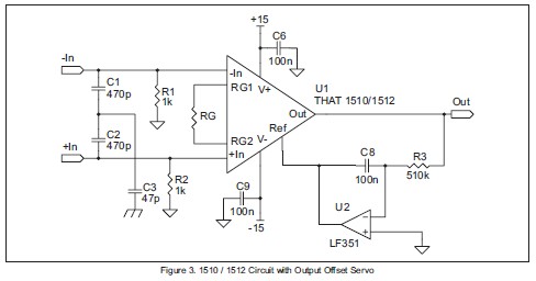
Image Courtesy of THAT Corporation
The circuit shown above "pins" the output baseline to near 0 volts, but does nothing to reduce pot scratch or switch clicking because it does not reduce the terminal voltage across Rgain. This servo works "after-the-fact" by feeding error correction into the Ref pin.
"Phantom Menace," the AES paper published by Hebert and Thomas, shows a servo circuit which senses the error at the Rgain pins and feeds that error back into the input:
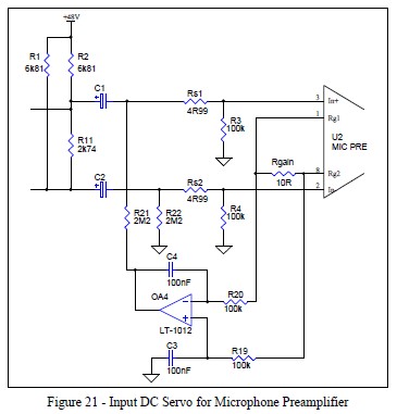
Image Courtesy of Audio Engineering Society
http://www.aes.org/e-lib/browse.cfm?elib=10028
The motivation for the input servo described in "Menace" is to reduce input offset caused by the 100k bias resistors. High value bias resistors, as opposed to the more typical 1k, were used to illustrate the benefits of low-value input capacitors and the reduced stored charge dumped during phantom power faults. 100k values allow, at the expense of current noise, the input capacitors to be made as low as 2 uF. Although it is often cited, I do not recommend this circuit.
The "Menace" circuit has been adapted for applications using low-value (typically 1-10k Ohm) bias resistors.
The effectiveness of this servo at reducing clicks and pot scratch is rather limited. There are a number of reasons for this:
1) The input voltage offset of the error amplifier must be significantly lower than the offset voltage being corrected. At 60 dB gain, the Rgain terminal voltage should be less than 10 uV to keep clicking low. An expensive LT1012 ($7.70 qty 1) is marginal in this application. An affordable OP07 has almost as much offset as the 1510 or 1512 itself.
2) High value input resistors must be used in the error amplifier to prevent loading the 1510/1512 Rgain nodes. At the required 100k, the servo amp's bias current error (Ibias*Rin) becomes significant.
3) Vos and bias current errors can be trimmed out, but the 0.6 uV/deg C drift (and Ibias drift) of the LT1012 still causes significant errors.
The device measuring the error has to be so much better than the 1510 or 1512 that a servo directly sensing Rgain terminal voltage is not practical. But, what about indirect measurement?
What if the THAT1510 or 1512 were used to measure it's own offset?
Remember that the worst-case output offset is defined, in millivolts, as (0.25*Gain)+/-5 mV. The (worst case) 250 uV of Rgain terminal voltage amplified by the 1510 gain allows us to improve, at 60 dB gain, our DC measurement capability 1000-fold. 250 uV at the Rgain pins becomes 250 mV at the output.
Sensing the error at the output, shown in the first figure, but applying correction to the input, as shown in the second figure, provides numerous advantages. Two significant advantages are 1) reduction in the required precision of the error amplifier/servo and 2) reduction of Rgain terminal voltage in order to reduce clicking and scratching.
Using an OP07 op amp at the output of the 1510, with typically 100 uV of input Vos and bias current error, only requires 100 nV at the input to satisfy it's own error when the gain is 1000 (60 dB). At high gains, the 1510s own internal gain is "helping" the error amplifier's precision.
At low gains however the 1510s internal output amplifier offset, the "+/- 5 mV" term, works against us. Although clicking at high gain is virtually eliminated, clicking at low gain is quite severe. The servo "sees" offset at Rgain which does not really exist. The key is to make the 1510 DC-accurate at low gains.
Without some means of eliminating the low gain offset error we've only moved the problem to the other "end of the dial." Fortunately for us, the low gain error is fixed and constant. Here's the solution:
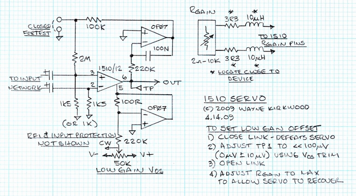
1510_Servo_Schematic.jpg
By defeating the servo during test and adjusting the low gain output offset to <10 uV the 1510 is made DC-accurate. The fixed "5 mV" term is trimmed out. With the servo re-connected for operation, the variable "0.25*Gain" error is servo'd. Thus, clicking at all gain ranges is significantly reduced because the Rgain DC terminal voltage is minimized by correction applied to the input.
The test 1510 was fairly typical, having uncorrected output offset of 1.34 mV (at unity gain) and an uncorrected Rgain terminal voltage of ~174 uV. With the servo operational the output was pinned, under steady-state conditions to approximately 100 uV essentially the combined errors of the OP07 servo and low gain Vos adjustment. The low gain offset adjustment range is about +/- 7 mV.
Worst-case clicking occurs during rapid slewing from low gain to high. This is the output rapidly switching from low to high gain (+6 to +60 dB) without low gain Vos adjustment:
1510_Servo_No_Output_Offset_Correction.jpg
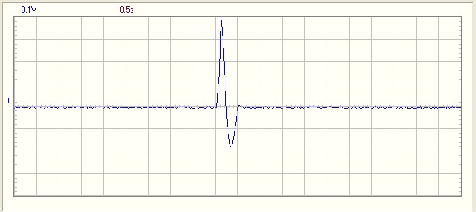
This is the output with low gain offset adjustment:
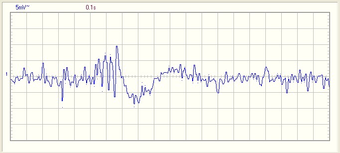
1510_Servo_With_Output_Offset_Correction.jpg
With low gain offset correction we go from 600 mV p-p to about 15-20 mV p-p - an improvement of about 30 dB.
Unless someone is in the habit of rapidly rotating gain controls with reckless abandon it's doubtful that even 15 mV would be produced. For the most part, gain change clicks are buried in the noise floor - and, to hear them - the monitoring level has to be quite high. In the last image you can see about 5 gain steps before the servo recovers. From the middle of rotation to either end, or from top to bottom, clicking is almost inaudible.
In my tests I estimated that the rotary switch was slewing from minimum to maximum gain in about 300-600 ms. I felt like I was abusing the switch and expected springs to come flying out. Rotating a fairly stiff pot that fast proved difficult.
The 10 uH inductors in the Rgain line are not essential but I recommend them. There can be rectification of HF and VHF frequencies above the small-signal bandwidth and at the very low voltages and offsets of this circuit they can also add to clicking. With 10 uH inductors the - 3dB point, at maximum gain, is about 80 kHz. Remember that in any preamp the input lines and Rgain lines should remain tightly balanced and loop areas kept small. I recommend that the inductors and Rstop resistors be as close to the device as possible.
I learned a fair amount about phantom coupling caps doing this exercise. I'll save that for another day...
Conclusion
OP07s are cheap, in qty 1 they run about $0.77 each. Two OP07s, and a trimmer, are a lot less expensive than a single LT1012. And, it works a lot better than anything I tried.
Without a large value (3300 uF typ) series capacitor in the Rgain line, the THAT1510 or 1512s worst-case output offset is defined, in millivolts, as (0.25*Gain)+/-5 mV. The +/- 5mV term is essentially the offset of the output differential amplifier and the (0.25*Gain) term the amplified 250 uV input error. Without a Cgain, the DC error at the output can be as high as 255 mV. (Neglecting Ios bias current errors.) In addition, the <=250 uV terminal voltage across Rgain, when amplified, will make pots sound scratchy when rotated or cause stepped gain switches to click. The primary objective is to keep the terminal voltage across Rgain <<10 uV.
The original 1510 data sheet (now replaced) shows an output servo amplifier.
Image Courtesy of THAT Corporation
The circuit shown above "pins" the output baseline to near 0 volts, but does nothing to reduce pot scratch or switch clicking because it does not reduce the terminal voltage across Rgain. This servo works "after-the-fact" by feeding error correction into the Ref pin.
"Phantom Menace," the AES paper published by Hebert and Thomas, shows a servo circuit which senses the error at the Rgain pins and feeds that error back into the input:
Image Courtesy of Audio Engineering Society
http://www.aes.org/e-lib/browse.cfm?elib=10028
The motivation for the input servo described in "Menace" is to reduce input offset caused by the 100k bias resistors. High value bias resistors, as opposed to the more typical 1k, were used to illustrate the benefits of low-value input capacitors and the reduced stored charge dumped during phantom power faults. 100k values allow, at the expense of current noise, the input capacitors to be made as low as 2 uF. Although it is often cited, I do not recommend this circuit.
The "Menace" circuit has been adapted for applications using low-value (typically 1-10k Ohm) bias resistors.
The effectiveness of this servo at reducing clicks and pot scratch is rather limited. There are a number of reasons for this:
1) The input voltage offset of the error amplifier must be significantly lower than the offset voltage being corrected. At 60 dB gain, the Rgain terminal voltage should be less than 10 uV to keep clicking low. An expensive LT1012 ($7.70 qty 1) is marginal in this application. An affordable OP07 has almost as much offset as the 1510 or 1512 itself.
2) High value input resistors must be used in the error amplifier to prevent loading the 1510/1512 Rgain nodes. At the required 100k, the servo amp's bias current error (Ibias*Rin) becomes significant.
3) Vos and bias current errors can be trimmed out, but the 0.6 uV/deg C drift (and Ibias drift) of the LT1012 still causes significant errors.
The device measuring the error has to be so much better than the 1510 or 1512 that a servo directly sensing Rgain terminal voltage is not practical. But, what about indirect measurement?
What if the THAT1510 or 1512 were used to measure it's own offset?
Remember that the worst-case output offset is defined, in millivolts, as (0.25*Gain)+/-5 mV. The (worst case) 250 uV of Rgain terminal voltage amplified by the 1510 gain allows us to improve, at 60 dB gain, our DC measurement capability 1000-fold. 250 uV at the Rgain pins becomes 250 mV at the output.
Sensing the error at the output, shown in the first figure, but applying correction to the input, as shown in the second figure, provides numerous advantages. Two significant advantages are 1) reduction in the required precision of the error amplifier/servo and 2) reduction of Rgain terminal voltage in order to reduce clicking and scratching.
Using an OP07 op amp at the output of the 1510, with typically 100 uV of input Vos and bias current error, only requires 100 nV at the input to satisfy it's own error when the gain is 1000 (60 dB). At high gains, the 1510s own internal gain is "helping" the error amplifier's precision.
At low gains however the 1510s internal output amplifier offset, the "+/- 5 mV" term, works against us. Although clicking at high gain is virtually eliminated, clicking at low gain is quite severe. The servo "sees" offset at Rgain which does not really exist. The key is to make the 1510 DC-accurate at low gains.
Without some means of eliminating the low gain offset error we've only moved the problem to the other "end of the dial." Fortunately for us, the low gain error is fixed and constant. Here's the solution:
1510_Servo_Schematic.jpg
By defeating the servo during test and adjusting the low gain output offset to <10 uV the 1510 is made DC-accurate. The fixed "5 mV" term is trimmed out. With the servo re-connected for operation, the variable "0.25*Gain" error is servo'd. Thus, clicking at all gain ranges is significantly reduced because the Rgain DC terminal voltage is minimized by correction applied to the input.
The test 1510 was fairly typical, having uncorrected output offset of 1.34 mV (at unity gain) and an uncorrected Rgain terminal voltage of ~174 uV. With the servo operational the output was pinned, under steady-state conditions to approximately 100 uV essentially the combined errors of the OP07 servo and low gain Vos adjustment. The low gain offset adjustment range is about +/- 7 mV.
Worst-case clicking occurs during rapid slewing from low gain to high. This is the output rapidly switching from low to high gain (+6 to +60 dB) without low gain Vos adjustment:
1510_Servo_No_Output_Offset_Correction.jpg
This is the output with low gain offset adjustment:
1510_Servo_With_Output_Offset_Correction.jpg
With low gain offset correction we go from 600 mV p-p to about 15-20 mV p-p - an improvement of about 30 dB.
Unless someone is in the habit of rapidly rotating gain controls with reckless abandon it's doubtful that even 15 mV would be produced. For the most part, gain change clicks are buried in the noise floor - and, to hear them - the monitoring level has to be quite high. In the last image you can see about 5 gain steps before the servo recovers. From the middle of rotation to either end, or from top to bottom, clicking is almost inaudible.
In my tests I estimated that the rotary switch was slewing from minimum to maximum gain in about 300-600 ms. I felt like I was abusing the switch and expected springs to come flying out. Rotating a fairly stiff pot that fast proved difficult.
The 10 uH inductors in the Rgain line are not essential but I recommend them. There can be rectification of HF and VHF frequencies above the small-signal bandwidth and at the very low voltages and offsets of this circuit they can also add to clicking. With 10 uH inductors the - 3dB point, at maximum gain, is about 80 kHz. Remember that in any preamp the input lines and Rgain lines should remain tightly balanced and loop areas kept small. I recommend that the inductors and Rstop resistors be as close to the device as possible.
I learned a fair amount about phantom coupling caps doing this exercise. I'll save that for another day...
Conclusion
OP07s are cheap, in qty 1 they run about $0.77 each. Two OP07s, and a trimmer, are a lot less expensive than a single LT1012. And, it works a lot better than anything I tried.