This thread replaces a previous "sneak preview" in which I described various input/output circuits for the 1570. Many of the designs can also be adapted to the 1510 and 1512. I agreed to replace it once THAT's DN-140 was published.
http://www.thatcorp.com/datashts/dn140.pdf
THAT 1570 1510 and 1512 Input/Output Circuits
-
mediatechnology

- Posts: 5457
- Joined: Sat Aug 11, 2007 2:34 pm
- Location: Oak Cliff, Texas
- Contact:
Re: THAT 1570 1510 and 1512 Input/Output Circuits
Nice reading!
Do you have any idea of a price these ICs are going to be sold in DIY quantities?
And where? I usually buy THAT chips at Farnell, they don't have them (yet).
I thought about doing something like a 4 channel remote preamp just for the fun
of it. Not that I actually need the remote functionality, but I like the combination
of analog electronics and programming...
Volker
-
mediatechnology
- Posts: 5457
- Joined: Sat Aug 11, 2007 2:34 pm
- Location: Oak Cliff, Texas
- Contact:
Re: THAT 1570 1510 and 1512 Input/Output Circuits
Thanks for posting hazmo.
I have no idea what pricing is going to run in small quantities.Do you have any idea of a price these ICs are going to be sold in DIY quantities?
You can get small quantities of them mounted on DIP adapters for prototyping from THAT. They have both the 1570 and 5171. There's also a demo board available. Soldering/removing those QFNs is no fun. I don't know when they'll be in distribution.And where? I usually buy THAT chips at Farnell, they don't have them (yet).
Re: THAT 1570 1510 and 1512 Input/Output Circuits
Thanks Wayne!
Concerning the availability, I'm not in a hurry, too many other projects in the line anyway.
But when I see something new I can't keep the ideas from popping up .
.
I think it will be interesting to see these devices in actual products. Performance is more
or less dictated by the board layout and the environment (PSU, ...) only. Circuit wise everything
is already there from the datasheet, you just have to add the digital control. I'm curious to
see if that will result in relatively similar products from several manufacturers, given how
you are "forced" into a design by ICs that are specialized to such a high degree.
For soldering QFN there are several possibilites, like oven and paste or a heat gun.
Also soldering by iron does the job well if you're used to SMD work. But it depends on
how far up the contacts of the chip go on its sides.
Volker
edit: I just did a quick search, should have done that in the first place. I found them at Mouser.
And frankly, they are quite moderately priced compared to what I expected.
Concerning the availability, I'm not in a hurry, too many other projects in the line anyway.
But when I see something new I can't keep the ideas from popping up
I think it will be interesting to see these devices in actual products. Performance is more
or less dictated by the board layout and the environment (PSU, ...) only. Circuit wise everything
is already there from the datasheet, you just have to add the digital control. I'm curious to
see if that will result in relatively similar products from several manufacturers, given how
you are "forced" into a design by ICs that are specialized to such a high degree.
For soldering QFN there are several possibilites, like oven and paste or a heat gun.
Also soldering by iron does the job well if you're used to SMD work. But it depends on
how far up the contacts of the chip go on its sides.
Volker
edit: I just did a quick search, should have done that in the first place. I found them at Mouser.
And frankly, they are quite moderately priced compared to what I expected.
Re: THAT 1570 1510 and 1512 Input/Output Circuits
Here is a quick sketch of what I had in mind for the audio part of the preamp.
Pretty much straight from the datasheets and the application note from the first post.
Not sure yet if I want to cram in a HPF or not.
The only thing I miss is something like an overload flag like the PGA2500 has. The digital
gain control just lends itself perfectly to reduce gain during overload conditions. I might
still try it because I was planning on sampling the signal anyway for metering purposes.
But the overload is supply voltage dependent and that makes it a bit tricky. On the other
hand with the available headroom it might be meaningless anyway. Hm, just throwing
thoughts around here .
.
Pretty much straight from the datasheets and the application note from the first post.
Not sure yet if I want to cram in a HPF or not.
The only thing I miss is something like an overload flag like the PGA2500 has. The digital
gain control just lends itself perfectly to reduce gain during overload conditions. I might
still try it because I was planning on sampling the signal anyway for metering purposes.
But the overload is supply voltage dependent and that makes it a bit tricky. On the other
hand with the available headroom it might be meaningless anyway. Hm, just throwing
thoughts around here
-
mediatechnology
- Posts: 5457
- Joined: Sat Aug 11, 2007 2:34 pm
- Location: Oak Cliff, Texas
- Contact:
Re: THAT 1570 1510 and 1512 Input/Output Circuits
Nice work.
K3 is a nice touch. Do you suppose that in the shunt position of K3 that you might want a small 10 Ohm (or less) resistor to limit the contact current whilst discharging the 47 uF? I know it adds another 20R source impedance but the relay may last longer.
You also might want to consider making the output stage gain -5.6 dB so you can have true unity gain. If you do that I'd lower the Rfb, Rsense values (R14 and R15).
I see that you followed the compensation in the output stage. Very good. (The demo board sch still has the error.) I found the overshoot problem that results when the values of the diff amp's Cc s are made too small. Those ratios are going to give you good differential transient performance. (If you scale R14 and R15 scale Cfb Cref). Neither Birt, nor later Jung/ADI (citing Birt), addressed the transient performance of that circuit. As they were originally shown overshoot was almost 50%. It's <<5% IIRC now (common mode) and nicely rounded differentially.
Have you looked at using a simple PhotoMos relay for phantom switching? The PS7113-2A is perfect for a "type A" which I normally recommend if constant input impedance is desired. You show a type C which is perfect since you're shunting Cin with K3 for I assume a "ribbon/dynamic" mode (does K3 always operate after phantom is turned off?) and you don't have to deal with the discharge of Cin by the phantom network. For a type B or C you could use a PS7113-1. With the PhotoMos you can simple drive the LED from a GPO (#3 is the one to use for sure) through a series R and you're done. The back-to-back NMOS on the load side also eliminates two Qs and some Rs etc. I've used them and they work great and are cheap.
Re: THAT 1570 1510 and 1512 Input/Output Circuits
The plan for K3 was that it will always be pre/post delayed to the switching of P48 until the caps are discharged/before they are charged, so that there will never be any current through the relay. K3 will always be active whenever P48 is not on, not controllable by the user.
I know those MOS relays you mention, I stumbled upon them when looking for non-mechanical relays for tube guitar amp builds (in the end I chose to use those, cool little thingies and HV compatible). Still I will stick to the transistor switching here I think. Not only is it something like 30c for the two transistors plus the resistors, the main reason is easy availabilty, I could even buy those at my local electronics shop. I try not to use any special parts when they are not really mandatory.
Good point with the unity gain. Though you could still get unity or less by engaging the pad. Ah, I see you were saying "true". I just simulated the output stage to find good values for the resistors. I couldn't get it to overshoot though, only really small ripple even without any compensation.
-
mediatechnology
- Posts: 5457
- Joined: Sat Aug 11, 2007 2:34 pm
- Location: Oak Cliff, Texas
- Contact:
Re: THAT 1570 1510 and 1512 Input/Output Circuits
OK, that's what I thought. K3 is linked to P48 control. That's cool.hazmo wrote:The plan for K3 was that it will always be pre/post delayed to the switching of P48 until the caps are discharged/before they are charged, so that there will never be any current through the relay. K3 will always be active whenever P48 is not on, not controllable by the user.
How many discharge time constants do you suppose you'll wait before turning K3 on? You might want to "back" ground the 6K81s when P48 is off to speed that up. (Type A).
The 100K+6K81 that's shared (~214k) for discharging the 47 uF x2 has a tau of around 20 seconds. At one TC Cin still have 37% of whatever the P48 started at. If the input was unloaded and P48 was 48V, then that's about 18V. With a modest ESR cap I think you'll see some fairly high peak currents unless you want to wait quite awhile to shunt it.
If the 6K81s were grounded when off (Type A), then the tau would be about 640 ms. At 5 TC, ~1% of P48 is 0.5V across Cin. K3's contact current, or the wait time, would be a lot less maybe 2-3 seconds. You might want to think about that.
BTW, if you open K3 but leave P48 off, you'll be amazed at how much stored charge (in the form of DA) comes back at you after Cin has been shorted. With aluminum electrolytics it can easily approach 4-5V after 15 minutes. This will probably never be an operating condition but the effect of DA on DC conditions deserves some additional exploration.
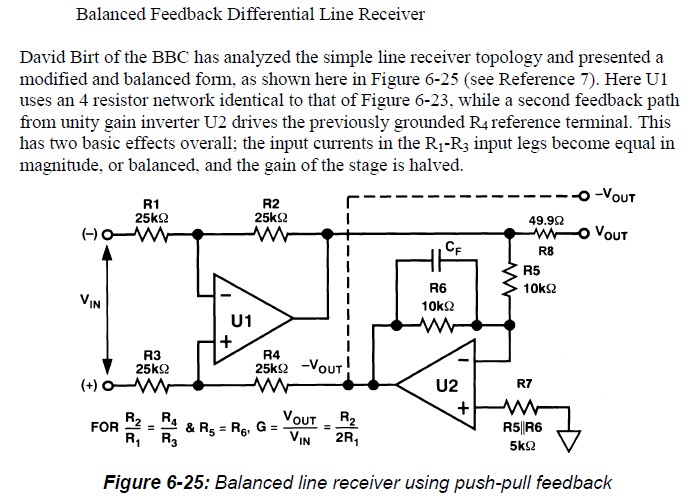
The output circuit relies on subtraction using inversion of the non-inverting output summed via the "ground" connection to the input reference resistor. As the delay in the inverter increases relative to differential stage, subtraction does not occur immediately and is delayed causing squarewave overshoot with real op amps. Although it does not sim that way, without compensation it will also oscillate. Here's the ADI/Jung cite of Birt's line receiver using the same topology:hazmo wrote:Good point with the unity gain. Though you could still get unity or less by engaging the pad. Ah, I see you were saying "true". I just simulated the output stage to find good values for the resistors. I couldn't get it to overshoot though, only really small ripple even without any compensation.
Here's an example of the overshoot with small, ~20 pF, caps for the inverter and differential amp typical of the schematic above built with 5532/2114s. (Note that the above sch doesn't have any caps in the diff amp shunting R2 and R4 which make it slightly worse than the image below.)
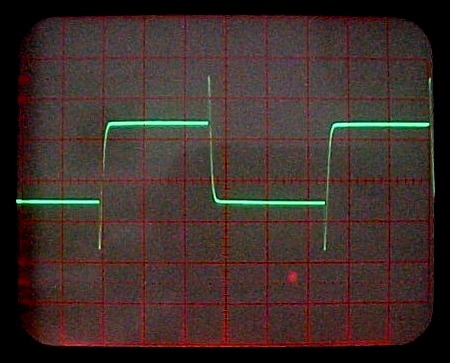
Birt_Output_Inverter_Output_20kHz_1.JPG
I think you could trick the simulator into producing real-world overshoot by making the inverter's Cc very large. It may sim well with no Cc or small values of differential Cc but trust me, with the differential amp as fast, or faster than the inverter, it overshoots by a bodacious amount when probed by an oscilloscope. Also when looking at the output look not only at the CM output (each relative to ground) but the differential one. I tuned the Cc values to the differential component and got lucky with the CM.
If you tune the differential amp to make it slower than the inverter you can clean the squarewave response up. I'm not sure I have photos of the basic output (these are for an A/D driver with Cload tolerance based on the same circuit) but this is about what you can get approximately:

A-D_Driver_Birt-Hebert_Full_Symmetry_Differential_20kHz.JPG. The above is the 20 kHz differential output response.

A-D_Driver_Birt-Hebert_Full_Symmetry_Out+_vs_Out-_20kHz.JPG. This is the + and - outputs relative to ground. Note the significant reduction in overshoot compared to the "stock" Birt circuit.
Re: THAT 1570 1510 and 1512 Input/Output Circuits
Thanks Wayne, great info! I tried to make the inverter fairly slower, but still no "success" .
Anyway, it's not that I didn't believe you, just wanted to see it myself. So thanks for the pictures!
Actually, I didn't even think too much about the time constants yet, but you're right. Should
have seen in the first place that it won't be really practical without shunting the 6,8ks to ground.
And so the MOS relays are back in the game, with that additional switching any transistorized
version gets too bloated. The PS7141 would be a good candidate with the complementary
switches, but Digikey says it's not recommended for new designs. Functionally similar is the
LCC110, and looks pretty good.
But I'll look further when I finally get around to do a pcb design, who knows what is available then.
Volker
-
mediatechnology
- Posts: 5457
- Joined: Sat Aug 11, 2007 2:34 pm
- Location: Oak Cliff, Texas
- Contact:
Re: THAT 1570 1510 and 1512 Input/Output Circuits
The PS7113-2 is a dual you might consider. Mouser stock them.
You can have one LED tied to the 3V3 line and the other one tied to ground (both using limiting resistors of course) to use a single logic line to make a SPDT switch. That way you can get the compliment using only one logic line. (Just make sure the driver doesn't tri-state or they'll both turn on. )
)
The 74LV125 (3V3) makes a good buffer with ample current to drive the LEDs. I wouldn't use the GPO output directly.
You can have one LED tied to the 3V3 line and the other one tied to ground (both using limiting resistors of course) to use a single logic line to make a SPDT switch. That way you can get the compliment using only one logic line. (Just make sure the driver doesn't tri-state or they'll both turn on.
The 74LV125 (3V3) makes a good buffer with ample current to drive the LEDs. I wouldn't use the GPO output directly.