
Paul Gold of Salt Mastering, a contributor here, has found ways to make the MS board do double and triple duty.
There are 13 ICs on the MS matrix board. Ironically, only four ICs are actually used for MS encode and decode. The majority of the MS Matrix circuitry are THAT1246 (or 1240) balanced inputs and THAT1646 balanced outputs. The 13th IC is an inverting 5532 stage which provides user-adjustable gain. Since there seems to be a pattern emerging for alternative applications for this board I thought it might be a good idea to revisit a 2009 post. I lifted this from the MS Matrix thread:
By removing the THAT1240 in the MS Matrix and using "B," "C," "F," and "G" as inputs and outputs, the board provides four line drivers and four line receivers.Back when we were in layout stage I sent Bob Katz a link to the thread and he suggested that we put insert points between virtually all of the stages. So we did.
After getting boards I sent Bob one to see what he thought. He saw uses for it I had completely overlooked. One of the ideas he had was to use the board as not only an MS matrix, the intended purpose, but as a muti input/output line balancing widget. With his permission I've quoted the e-mail he sent describing some "alternative" uses for the board. I've also been sent a "whitepaper" by Bob describing all the insert points that I need to edit and post.
Bob Katz wrote:
Hi, Wayne. Here's what I've been thinking of, in terms of adapting your board to a fully functional mastering system with insert points and balanced input and output buffers. I thought you might appreciate my thinking because in the end your board will make a powerful board for mastering engineers. In my case the board will be mounted in the analog processing rack.
1) Need for balanced receivers and drivers for the analog mastering system (which consists of various outboard analog processors). This is because my processing DAC and ADC (for the digital to analog insert) are mounted in a separate rack and I've found they perform more noise free if they feed and receive from the processing rack balanced. And some of my outboard gear (Pendulum OCL-2 compressor) have unbalanced inputs.
So, for the "independent" balanced receiver, hopefully this can be solved by using U1, and feeding point B to a "patch bay" (actually relays), breaking it at point B if the M/S encoder is not being used. Probably changing U1 for a 1240 to get unity gain if I can live with the headroom issues and work a complementary gain in the decoder side. Break out to a patch point to drive the external gear.
2) For the "independent" balanced line driver, adding a patch point at point G. And the inverting input to U9 adds some great versatility:
a) The 20K resistor can be replaced with an input pot and a 10K resistor for variable line driver gain up to 6 dB (more than enough). I use this as a trim point back into the ADC.
b) Parallel compression! Yes... Since U9's inverting input can be a summing point, it opens up the possibility for a summing point for a parallel compressor. So I plan on adding another 10K resistor to the inverting input and optionally patching the output of a compressor into there, probably using the compressor's gain makeup control as the parallel gain or else adding another pot. The onboard pot controls the "dry" level and the pot on the compressor controls the "wet". Doesn't that sound exciting!
This leaves us with an unbalanced input at point B for the M/S encoder which is also (incidentally) a balanced line driver.
And a balanced input decoder with an unbalanced patch point output at point G. I suppose I'd have to change U7 for a 1240 as well to keep the encode/decode at unity. We shall see how that affects the performance. Thank heaven for your dip sockets! We learn over the years to use sockets, don't we.
That's the most versatile board I can imagine. It's nice that your board is already up to the task. How does that sound to you?
Best wishes,
Bob
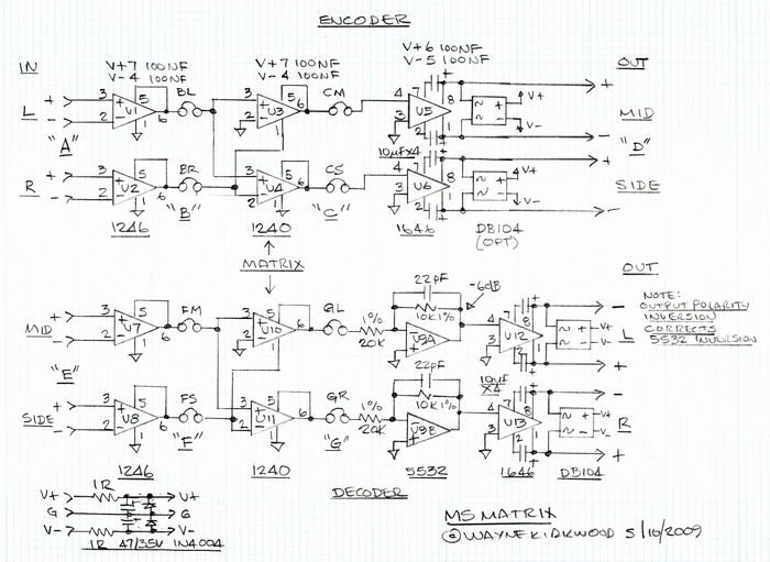
MS Matrix Board Block Diagram Showing Various Insert Points