Phono Transfer System Construction Information

Construction information for DIY projects, including the MS Mid Side Matrix, Elliptic Equalizer, Mastering Console, Phono Transfer System, Insert Switcher and the Dual Class-A Amplifier. You can post your baby pictures here.
Post Reply
User avatar
mediatechnology
Posts: 5469
Joined: Sat Aug 11, 2007 2:34 pm
Location: Oak Cliff, Texas
Contact:

Phono Transfer System: Preamp Enclosure

Post by mediatechnology »

The Flat Phono Preamp fits nicely in a Hammond 1590BBBK enclosure.
Paul suggested using 9 Pin D connectors to minimize panel space and it worked out nicely.
The preamp is designed to be remotely located at the turntable.
The Hammond 1590BB is 4.7" x 3.7" x 1.3" and is easily tucked away behind the turntable.

Image
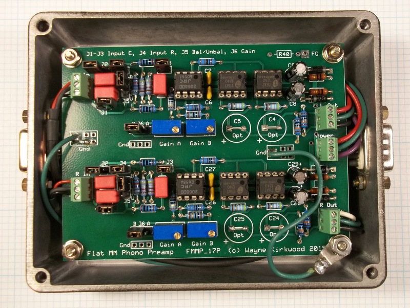
Balanced Input/Balanced Output Moving Magnet Flat Phono Preamp part of the Phono Transfer System.

The board sits above the D connectors on 5/8" spacers.
The metal case is tied directly to DC ground.
The turntable frame ground has it's own DB-9 pin which also ties to DC ground.
I found that a 100R resistor (R40) from DC ground to the frame works just as well.

The output coupling capacitors will not fit in the box but they really aren't needed.
The typical differential and common mode output offsets are in the millivolt range thanks to the balanced cart connection and common mode rejection stage.

Image
Balanced Input/Balanced Output Moving Magnet Flat Phono Preamp, Balanced Phono Input 9 Pin D Connector

The balanced phono inputs are on a female DB-9 connector.
The back shell is internally shielded with aluminum foil.
It's important the the DB-9 frame is grounded (or AC grounded) because there is about 1.5 pF capacitance from the frame to the pins.
After I took this pick I realized that the color codes for the outputs were reversed.
I always have a hard time remembering the Left is White...
So I reversed them and the inputs.

Image
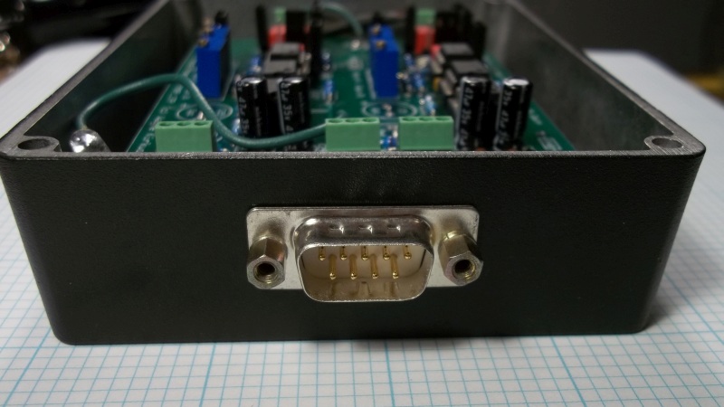
Balanced Input/Balanced Output Moving Magnet Flat Phono Preamp, Flat Phono Output 9 Pin D Connector

The flat balanced preamp outputs and bipolar DC power input are on a DB-9 male.
The DB-9s are pinned out so that DC will not appear on the cartridge if one were to absently-minded plug the input and output cables together.

At the present time the Flat Preamp is driving the RIAA EQ/Monitor Switcher through 50 feet of cable.
The balanced low-level cartridge cables are less than 3 feet long.
There is a lot of benefit to the balanced input connection and local gain.
Gold
Posts: 683
Joined: Sat Dec 01, 2007 5:20 pm

Re: Phono Transfer System

Post by Gold »

Wayne was kind enough to send me assembled and tested PCB's to build a Phono Transfer System. This is like a dream come true for me. I've always wanted something like this.

My needs are different than Wayne's so I built it up a bit different. My primary use is to interface with a lathe for playback. It's difficult to interface a phono pre to a Neumann lathe because the 0V bus is very polluted with current from pull down transistor switching. The audio electronics are almost totally separate. I also wanted my build to be able to stand up to torture tests. It should be impossible to make noisy. Even on a stage at 4AM with bad grounding, heinous dimmer noise and a drunk stage hand.

I went to great lengths to make sure this happened.

Image

I used an ABS plastic case and lined it with copper tape. I wanted to make it impossible for the remote pre to come in contact with any ground plane. You can see the nylon shoulder washers I used so the mounting screws don't touch the shielding.

Here is part of the grounding scheme. The binding post is DC coupled but the cable shield and cover are AC coupled.

Image

Here is the pre wired up. The umbilical cable runs Audio Common separate from Chassis. They meet at the service entrance.

Image

Here is a shot of the system. Getting there.

Image

Since I am primarily using this for monitoring and don't record much I wanted it to behave differently than Wayne. Here is the faceplate, which will be redone. Instead of "Record" and "Monitor" paths like Wayne I am calling the two paths "Phono" and "Line". The "Record Out" I'm calling "Phono Out" and the "Monitor Out" I'm calling "LIne Out". I have RY1 and RY2 tied together on the same switch. If RY1 is in "Play" (Line) then RY2 is in "EQ". In other words the left most switch switches the EQ from "Phono" to "Line". If the EQ is in the Phono path then "Line" path is flat.

I have RY3 on a switch. I would generally use the "Line Out" as a buffered record out if I need it. That way I can switch the EQ in and out of the Line or Record out.

I also will alter the gain at the trim in the Base Station. The rotary switch will have -12dB, -6dB, 0dB, +6dB,+12dB. The fine trims will be +/-6dB. So there will be 18dB of gain at the finger tips.

Image


Image

I just installed it tonight. It's scary quiet. Almost disconcerting. Sounds great too. The thing next to the base station is my console power test jig. Can't be too careful...


Image


Image
emrr
Posts: 573
Joined: Sun Mar 02, 2008 10:27 pm
Location: NC, USA
Contact:

Re: Phono Transfer System

Post by emrr »

Good work guys. I am tempted. Your bench looks about like mine!
Best,

Doug Williams
Electromagnetic Radiation Recorders
User avatar
mediatechnology
Posts: 5469
Joined: Sat Aug 11, 2007 2:34 pm
Location: Oak Cliff, Texas
Contact:

Re: Phono Transfer System

Post by mediatechnology »

Thanks very much Paul for all the hard work you've put into this.

It's very nice to see SN002 sitting on the back of a lathe.
Gold
Posts: 683
Joined: Sat Dec 01, 2007 5:20 pm

Re: Phono Transfer System

Post by Gold »

Thanks. It's going to be very flexible. I realized that with a 1:32 step up the Denon 103 wants to see a 100k load which is already there. I was using 1:16 before. I was going to use a second set of transformers for the SPU. Now all I have to do to change over to the SPU is put the right value parallel resistor in R1 and move the jumper and use Gain B. If I want o use an MM I can move the leads from the transformer input to the PCB input. Pretty slick.
Gold
Posts: 683
Joined: Sat Dec 01, 2007 5:20 pm

Re: Phono Transfer System

Post by Gold »

I did some more work on the gain switching I want. I set it up with the gain range I wanted and the fine trim.

Image

+/- 6dB wasn't a fine enough resolution for me so I tried +/- 3dB. Still no good. I am using this primarily for reference listening so I want it calibrated within 0.1dB. Time to ditch the fine trim idea. Since I have 12 position switches I decided to go for +/- 18db. -18,-12,-9,-6,-3,0+3,+6,+9,+12,+18. After spending some quality time with a resistor substitution box I decided against going to +18dB. The feedback resistor would have had to be 300k which seemed a bit much to me. So +/- 12dB it is. Unfortunately when I got through with everything I realized I got the range wrong. Now it goes from -18dB - +9dB. Ooops. I'll fix that eventually and publish my values.

Image

The switch wiring is how I want it. I decided to dump the switch for RIAA Encode/Decode. It would be a rare use and running wires around might be counter productive. I can move the jumpers if I ever need it. I have RY2 and RY3 tied together. When RY2 is NC RY3 is NO and the other way round. That switch is called RIAA EQ and it chooses Phono/Line. RY4 is the Line Out choosing EQ or flat. RY1 stays NC so no connection necessary.

Image

Here is a shot of it calibrated using the AP Portable One as the signal source. It has the 1:32 step up transformer at the input.

Image

I have an intermittent 3dB noise floor discrepancy between the channels. Of course when I went to take the photo it wouldn't go away.

Image

Still sounds great.
Last edited by Gold on Sun Sep 20, 2015 7:53 pm, edited 3 times in total.
ricardo
Posts: 262
Joined: Sun Apr 10, 2011 7:24 am

Re: Phono Transfer System

Post by ricardo »

mediatechnology wrote:This is the construction thread for the Flat Phono Preamp and RIAA EQ/Monitor Switcher that evolved from the discussion here: viewtopic.php?f=6&t=423
This is great stuff Wayne. Electronics for the ultimate vinyl system :ugeek:
The ATR-96 MM cartridge is rated 5mv at 5 cm/s 1 kHz. They don't specify whether modulation is mono or single-channel.
They shouldn't have to. It's related to the mechanical motion. If you have single channel modulation, the sens. is for single channel. If you have mono, its the sens. for mono playback (L+R)
I later found that the OPA2134 is actually better with a cart, compared to a resistor, due to its lower current noise.
In the midrange the NJM2068, NJM2114 or NE5532 out-perform the OPA2134 where it's higher voltage noise dominates.
Got some numbers or preferably some noise spectrum plots for this? Yes. I know it will vary with cartridge ;)

In the 80s & 90s, I would have said 5532/4 was almost perfect for MM. Their Ropt for best noise is 7-9k. But I hadn't tried any of the 'new' uber FET OPAs. (I'd tried OPA2134 but not for low noise. What impressed me then was its immunity to RFI and poor layout.)

For a really Gold plated version, you could use OPA 627 which is FET i/p, Env 4nV/rt(Hz) like 5532, zillion V/us & $$$ :mrgreen:
User avatar
mediatechnology
Posts: 5469
Joined: Sat Aug 11, 2007 2:34 pm
Location: Oak Cliff, Texas
Contact:

Re: Phono Transfer System

Post by mediatechnology »

Paul - You might want to cut the wire ties bundling the left channel gain switch to the right channel input leads and re-route the left gain switch separately. That might be introducing a capacitive imbalance in either the right channel input or left channel front-end.

I had one channel that also had more hum ingress depending on arm position with the AT-96. It was quiet on or over the platter but had a slight rise when on the tonearm rest. The AT-96 does not have an external grounding strap but it sure acted like it had an internal one. Upgrading to the Stanton 681 moved the hum to the other channel - removing the grounding strap made them both equally quiet.
This is great stuff Wayne. Electronics for the ultimate vinyl system :ugeek:
Thanks!
I later found that the OPA2134 is actually better with a cart, compared to a resistor, due to its lower current noise.
In the midrange the NJM2068, NJM2114 or NE5532 out-perform the OPA2134 where it's higher voltage noise dominates.

Got some numbers or preferably some noise spectrum plots for this? Yes. I know it will vary with cartridge ;)
When I ran that experiment previously it was with the aforementioned AT-96 having the reference NJM2068 in the left channel and the DUT in the right.
So there may have not been a noise disadvantage for the OPA2134.
Not originally knowing the AT-96 had some imbalance and now having the benefit of the preamp being in a sealed metal box I should retest.

I still the think NJM2068 is the one to beat: viewtopic.php?f=6&t=423&start=214
Gold
Posts: 683
Joined: Sat Dec 01, 2007 5:20 pm

Re: Phono Transfer System

Post by Gold »

mediatechnology wrote:Paul - You might want to cut the wire ties bundling the left channel gain switch to the right channel input leads and re-route the left gain switch separately. That might be introducing a capacitive imbalance in either the right channel input or left channel front-end.
The imbalance was there before I put in the switch. I thought I had got rid of it. It was at the input. I redid that wiring. I suppose it could have switched places. I didn't try to chase it down yesterday as I was concentrating on resistor switch values.
Gold
Posts: 683
Joined: Sat Dec 01, 2007 5:20 pm

Re: Phono Transfer System

Post by Gold »

I removed the old Shure SE22 phono pre I was using today. I'm all in. I'm going to build a "demo unit" and pass it around. I'm very curious to get feedback from others (mostly cutters). First I need to finish restoring the lathe I'm supposed to deliver in six weeks...At least I got this build mostly out of my system.
Post Reply