Flat Moving Magnet Preamp New Layout with Gain Header
Posted: Mon Apr 02, 2018 4:33 pm
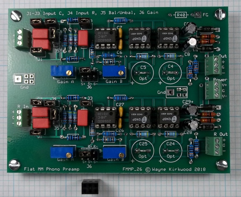
I have just received a new layout for the Flat Moving Magnet Preamp for the Phono Transfer System.
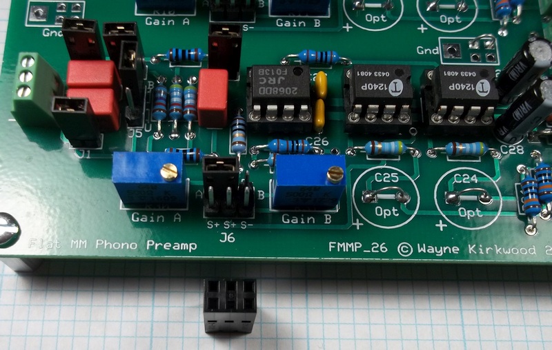
The new board is identical electrically and mechanically to the original with the exception of the addition of a 6 pin Gain header. There is also a minor expansion of the ground plane "keep out" area under the dual op amps.
The additional pins have connections for driven shields (thanks JR!) to minimize cable capacitance when external gain switching is used. The external gain can be either a DPDT switch to alternate between preset A and B gains, or it can be configured to switch Rgain for stepped gain control.
Molex "CGrid-III" housings mate with the header to allow external connections or on-board jumper shunts.
I'll post an image of the gain cables once I receive my ultra-miniature Mogami console cable.
Flat Balanced Input Moving Magnet Preamp
Flat Balanced Input Moving Magnet Preamp
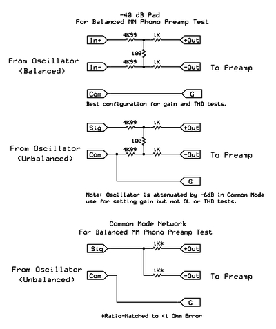
I also did a Common Mode Rejection test.
Rsource is 1 KΩ per leg matched within about 0.5Ω.
The gain is +22 dB so the measured CMRR numbers, referred to the input, are 22 dB better than shown.
Sweeps are done with Cterm = 0, 50, 100 and 200 pF. (150 pF not shown).
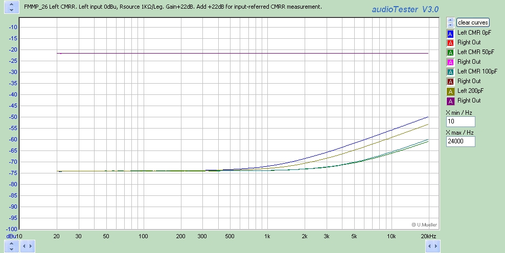
The top trace is the right channel output with the input differentially driven at -44 dBu and with 22 dB gain.
(The right channel does not provide any reference for the left channel and should be ignored.)
The bottom traces are the left channel CMRR with the input driven at 0 dBu through 1KΩ resistors matched within 0.5Ω.
The left channel differential gain is 22 dB.
The CMRR at 60 Hz, referred to the input, is about 96 dB.
There is, as expected, some effect of Ctermination on CMRR. The best combinations at HF are with J3 open where the CMRR at 20 kHz is still a respectable 70 dB.
The new board is identical electrically and mechanically to the original with the exception of the addition of a 6 pin Gain header. There is also a minor expansion of the ground plane "keep out" area under the dual op amps.
The additional pins have connections for driven shields (thanks JR!) to minimize cable capacitance when external gain switching is used. The external gain can be either a DPDT switch to alternate between preset A and B gains, or it can be configured to switch Rgain for stepped gain control.
Molex "CGrid-III" housings mate with the header to allow external connections or on-board jumper shunts.
I'll post an image of the gain cables once I receive my ultra-miniature Mogami console cable.
Flat Balanced Input Moving Magnet Preamp
Flat Balanced Input Moving Magnet Preamp
I also did a Common Mode Rejection test.
Rsource is 1 KΩ per leg matched within about 0.5Ω.
The gain is +22 dB so the measured CMRR numbers, referred to the input, are 22 dB better than shown.
Sweeps are done with Cterm = 0, 50, 100 and 200 pF. (150 pF not shown).
The top trace is the right channel output with the input differentially driven at -44 dBu and with 22 dB gain.
(The right channel does not provide any reference for the left channel and should be ignored.)
The bottom traces are the left channel CMRR with the input driven at 0 dBu through 1KΩ resistors matched within 0.5Ω.
The left channel differential gain is 22 dB.
The CMRR at 60 Hz, referred to the input, is about 96 dB.
There is, as expected, some effect of Ctermination on CMRR. The best combinations at HF are with J3 open where the CMRR at 20 kHz is still a respectable 70 dB.