Dual Class-A II Line and Headphone Output Construction Information

Construction information for DIY projects, including the MS Mid Side Matrix, Elliptic Equalizer, Mastering Console, Phono Transfer System, Insert Switcher and the Dual Class-A Amplifier. You can post your baby pictures here.
Post Reply
User avatar
mediatechnology
Posts: 5437
Joined: Sat Aug 11, 2007 2:34 pm
Location: Oak Cliff, Texas
Contact:

Dual Class-A II Line and Headphone Output Construction Information

Post by mediatechnology »

This thread provides construction information for the Dual Class-A II "DCAO-2" Line and Headphone Output Board.

Dual Class-A II Headphone and Line Amplifier PC Board: https://ka-electronics.com/shop/index.p ... ch=class-a
Update September 26, 2022. Updated assembly instructions: https://ka-electronics.com/images/pdf/D ... 092622.pdf

Background Information

The DCAO2 is based on the original Dual Class-A concept of using a "common mode" signal drive and differential bias drive to control a BD139/BD140 NPN and PNP output pair. In the original Dual Class-A circuit, a THAT1646 or DRV134 line driver was used in an unconventional configuration where the Sense lines were driven by signal in "common mode" with a Vbe bias reference driving the "normal" differential input. The two outputs of the THAT1646 drive the current boost transistor bases. The NPN output is level-shifted up by the Vbe reference, the PNP output is "voltage-mirrored" down by the Vbe reference and both are driven together by signal.

The result is a DC-stable, high-linearity line or headphone output with very low distortion running open loop. With a high idle current, around 85-100 mA, low distortion outputs up to 100 mW are possible. The original discussion is located here: viewtopic.php?f=6&t=23


The DCAO2 Dual Class-A II Line and Headphone Amplifier improves on the original design to provide both voltage gain and optional global feedback.

The DCAO2 output current booster is identical to the original DCAO but the DCAO2 pre-driver circuit has been changed to use op amps which emulate the THAT1646 concept of common mode signal and differential bias drive. Though the THAT1646 and DRV134 are excellent devices it was found that the even-order distortion of the driver stage could be reduced further by trimming.

Higher bandwidth is also possible using a dual op amp driver. The DCAO2 rise time is about 100 ns, its' small-signal bandwidth is 3.5 MHz and its' slew rate about 20V/us. (Using LME49720s or OPA1612s.)

A gain stage has been added to the DCAO2 which permits optional closed loop operation. Global feedback extends the output capability of the DCAO-2 to several watts in Class A/B. At power levels below 100 mW, operation remains in Class-A.

The advantage of having closed loop operation at lower power levels is a reduction in output impedance.

The high linearity of the DCAO2 output running at 85-100 mA does not produce errors requiring corrective feedback at power levels below 100 mW. The benefit of feedback is reduced output impedance.

The open loop output impedance of the DCAO and DCAO2 is just under 2 Ohms. Running closed loop the DCAO2 closed loop output impedance is reduced to about 40 mΩ. With the DCAO2 the user can drive headphones with "0 Ohm" (40 mΩ) Rout, less than 2Ω (open loop) or with any Ro of their choosing.

Image
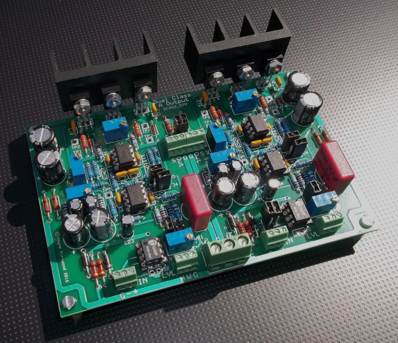
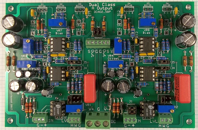
Dual Class-A II, DCAO2, Headphone and Line Amplifier PC Board

Image
Dual Class-A "DCAO2" Headphone and Line Amplifier Schematic

Mouser Project Manager link to the Dual Class-A II parts list: http://www.mouser.com/ProjectManager/Pr ... b5edbf3bcb

Dual Class-A II, DCAO2, Headphone and Line Amplifier assembly instructions: https://www.ka-electronics.com/images/p ... ions_7.pdf

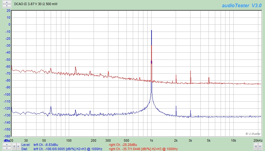
Some power and distortion measurements for the DCAO2 can be found here: viewtopic.php?f=6&t=799&start=32

A circuit description will soon follow.
User avatar
mediatechnology
Posts: 5437
Joined: Sat Aug 11, 2007 2:34 pm
Location: Oak Cliff, Texas
Contact:

Re: Dual Class-A II Line and Headphone Output Board Document

Post by mediatechnology »

I wanted to post a picture of a Dual Class-A II board being assembled for those who are just now receiving them.
This particular board is fully-assembled with the exception of the output transistors and has undergone initial DC tests.
The links are in the test position.

I'll be including this and other pictures in the pdf assembly instructions so you may want to check back and re-download them.

Image
Assembled Dual Class-A II Board before installing the output transistors.

This particular board is being assembled for headphones so the optional output build-out resistors are 33Ω.
I ship them with 0R build-out with J6 shunting the 33Ω.
Since the HPA will likely be used in a consumer environment the balanced inputs use THAT1240s.
"+4" builds should use THAT1246.
The LME49720 is the best all-around performer in this circuit.
The OPA1612 or FET OPA1642 on a DIP adapter is top-notch.
OPA2134, OPA260s and even the 2114 or 5532 do well.
User avatar
mediatechnology
Posts: 5437
Joined: Sat Aug 11, 2007 2:34 pm
Location: Oak Cliff, Texas
Contact:

Re: Dual Class-A II Line and Headphone Output Board Documents

Post by mediatechnology »

Update 2/8/2019: The schematic improperly reverses J4 and J5. J4 is the feedback jumper. An updated schematic will be posted soon.
User avatar
mediatechnology
Posts: 5437
Joined: Sat Aug 11, 2007 2:34 pm
Location: Oak Cliff, Texas
Contact:

Re: Dual Class-A II Line and Headphone Output Board Documents

Post by mediatechnology »

Dual Class-A II, DCAO2, Headphone and Line Amplifier assembly instructions: https://www.ka-electronics.com/images/p ... ions_7.pdf
User avatar
mediatechnology
Posts: 5437
Joined: Sat Aug 11, 2007 2:34 pm
Location: Oak Cliff, Texas
Contact:

Re: Dual Class-A II Line and Headphone Output Construction Information

Post by mediatechnology »

I made some DCAO-II measuerments in the Super Oscillator thread and have cross-posted the data here.
mediatechnology wrote: Thu Dec 03, 2020 2:04 pm
I have a spreadsheet I wrote to plug in the distortion levels from the FFT, subtract the gain, subtract the carrier level, add the filter insert loss, compute the ratio and then power sum HD2 to HD10 to obtain the THD.
THD is displayed as percent, parts per million and dBc.

This is the FFT of the DCAO-II headphone amplifier at 500 mW into 30Ω.

Image
FFT of the DCAO-II headphone amplifier at 500 mW into 30Ω.
Red is notch filter out. Blue is an attenuated sample of the output.
The DCAO-II and Uldo both have distortion that is less than the residual of the Focusrite 2i2's A/D.


Plugging the FFT data into the spreadsheet allows THD to be calculated.

Image
Spreadsheet calculates the THD of the DCAO-II to be 0.00023% based on FFT measurement of the notch filter output.
User avatar
mediatechnology
Posts: 5437
Joined: Sat Aug 11, 2007 2:34 pm
Location: Oak Cliff, Texas
Contact:

Re: Dual Class-A II Line and Headphone Output Construction Information

Post by mediatechnology »

Updated the assembly instructions and Mouser BOM.

https://ka-electronics.com/images/pdf/D ... 100121.pdf
Post Reply