The servo works great.
About the only issue I found was that large offset input pairs (≈1mV) tended to have less power supply rejection.
Originally I thought the collector loads were the source but it turned out it was the reference divider strings.
A simple capacitance multipler solved that problem.
In a typical preamp the reference string is common to both op amps.
Noise there appears in common mode.
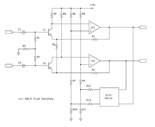
With the servo approach I borrowed from Olaf, a bridge is formed which has both a common mode and a differential offset correction component.
When the bridge is pulled harder to one side, common mode rejection of power supply noise apparently decreases from increased common mode to differential conversion.
FWIW the servo injection is high-level and not subject to differential gain which is cool.
With the values I chose the servo attenuation is only "4."
An input pair with 1 mV Vbe mis-match subject to 60 dB gain produces 1V offset at the output.
The differential offset voltage to correct this is only -4V or +/-2V at the servo outputs.
The servo correction voltage at the op amp non-inverting inputs is reflected at the input transistor collectors to equalize the emitter voltages and currents.
Ultimately I decided that I wanted a better-defined voltage for the collector loads and reference dividers than a cap multiplier could provide.
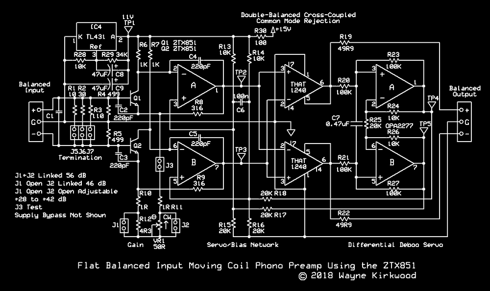
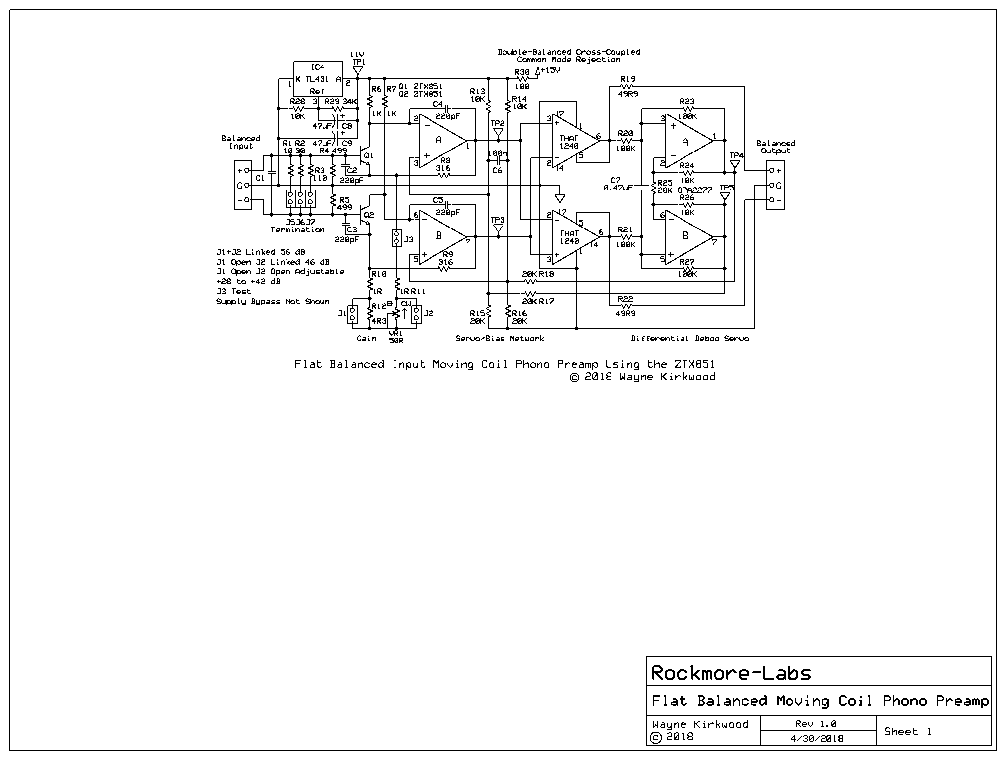
I looked at simple solutions and decided on a TL431 shunt regulator and an 11V sub-rail for the collector loads and reference dividers.
Cohen's circuit had two red LEDs to lower Vcc to about 11.3V with a 15V rail.
The reason he gave - a good one - was to limit the common mode range the following 5532 would see.
Having an 11V sub-rail seemed like a good idea not only from a noise perspective but also mindful of the following op amp's CM range.
The TL431 shunt regulator worked great. Along the way I decided to try an odd-ball idea that came to me and I became distracted:
viewtopic.php?f=6&t=960
Now that I have that out of my system I'll do some preamp drawings for us to look at.


