A Universal Input Using the THAT1570 and 5173
Posted: Thu Mar 29, 2012 2:21 pm
A couple of years ago I developed a "Universal Input" using a THAT1570 and 5171 where the 5171 U-Pad was switched to provide both gain and attenuation. This allowed "one knob" gain adjustment (via SPI) from ~ +60 dB to -50 dB.
The 5171 gain step arrangement required a work-around to overcome a 13.6 dB initial step size, (13.6dB to get to the 1 dB/step range). Both a 13.6 dB input pad and switched output gain stage were needed. The circuit worked quite well and I set it aside. Now that the THAT5173 is available with 0-60 dB in 3 dB steps, the circuit becomes incredibly simple.
The 5173 version is not tested - I'm waiting on samples - but results using the 5171 lead me to believe the following is doable:
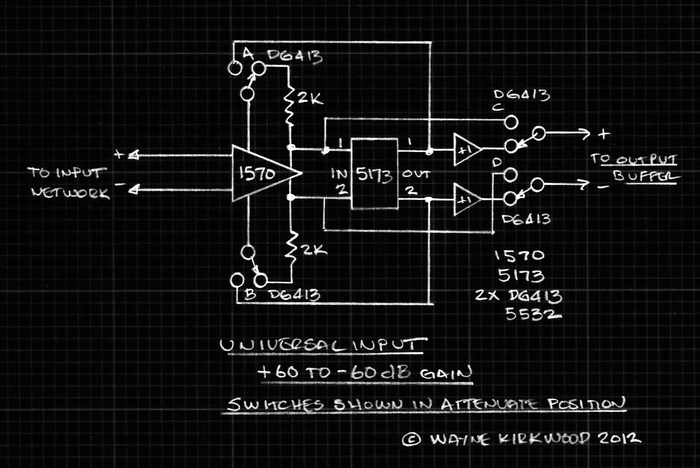
A Universal Input Using the THAT1570 and 5173.
The input network (bias resistors, 5173 servo, protection, coupling etc.) are not shown for clarity.
The concept:
Two DG413 packages switch the location of the 5173 U-Pad from providing feedback (gain) to being in-line with the output (attenuation).
The switches are shown in the Line (attenuation) position.
The 1570 acts as a voltage follower which drives the 5173 U-pad inputs.
The 5173 output is buffered by 5532-type voltage followers to prevent loading the 5173 pad and upsetting taper.
When the switches are in the Mic (gain) position, the 5173 provides feedback for the 1570.
This is the "conventional" connection of the 1570/5173 pair.
A second DG413 package switches the output buffer to either the 1570 outputs (gain) or the 5173 buffered output (attenuation).
A few notes:
The DG413 provides guaranteed "break-before-make" operation.
IIRC the typical "dead time" is about 20 ns.
The dead time is so short, neither the 1570 or +1 buffers see loss of bias current. (I didn't even use bias resistors for the 5532 since the attenuator and 1570 provide a DC path.)
(None of these parts are going to move in 20 ns.)
There is a one Vbe offset at the output of the 1570. The output buffer sees this in common mode. AC-coupling might be required.
My experiments did not switch gain/attenuation on zero cross, but during silence the transition was virtually clickless.
The 5173 Busy output and GPOs can be used to switch the DG413s, phantom on/off etc.
Another concern, unfounded, was the bias current noise of the 5532-type buffer.
It remains across the 1570's Rgain pins during gain.
Fortunately the bias current noise of the buffer is relatively small compared to the 1570's noise current at the Rgain pins. (The input stage emitters.)
Wrap-up:
I wanted to go ahead and publish this because the introduction of the THAT5173 made it so simple.
I'll keep updating this post once I get some samples.
As I understand it the 5173 is available now - I'm waiting for one on a DIP carrier.
The 5171 gain step arrangement required a work-around to overcome a 13.6 dB initial step size, (13.6dB to get to the 1 dB/step range). Both a 13.6 dB input pad and switched output gain stage were needed. The circuit worked quite well and I set it aside. Now that the THAT5173 is available with 0-60 dB in 3 dB steps, the circuit becomes incredibly simple.
The 5173 version is not tested - I'm waiting on samples - but results using the 5171 lead me to believe the following is doable:
A Universal Input Using the THAT1570 and 5173.
The input network (bias resistors, 5173 servo, protection, coupling etc.) are not shown for clarity.
The concept:
Two DG413 packages switch the location of the 5173 U-Pad from providing feedback (gain) to being in-line with the output (attenuation).
The switches are shown in the Line (attenuation) position.
The 1570 acts as a voltage follower which drives the 5173 U-pad inputs.
The 5173 output is buffered by 5532-type voltage followers to prevent loading the 5173 pad and upsetting taper.
When the switches are in the Mic (gain) position, the 5173 provides feedback for the 1570.
This is the "conventional" connection of the 1570/5173 pair.
A second DG413 package switches the output buffer to either the 1570 outputs (gain) or the 5173 buffered output (attenuation).
A few notes:
The DG413 provides guaranteed "break-before-make" operation.
IIRC the typical "dead time" is about 20 ns.
The dead time is so short, neither the 1570 or +1 buffers see loss of bias current. (I didn't even use bias resistors for the 5532 since the attenuator and 1570 provide a DC path.)
(None of these parts are going to move in 20 ns.)
There is a one Vbe offset at the output of the 1570. The output buffer sees this in common mode. AC-coupling might be required.
My experiments did not switch gain/attenuation on zero cross, but during silence the transition was virtually clickless.
The 5173 Busy output and GPOs can be used to switch the DG413s, phantom on/off etc.
Another concern, unfounded, was the bias current noise of the 5532-type buffer.
It remains across the 1570's Rgain pins during gain.
Fortunately the bias current noise of the buffer is relatively small compared to the 1570's noise current at the Rgain pins. (The input stage emitters.)
Wrap-up:
I wanted to go ahead and publish this because the introduction of the THAT5173 made it so simple.
I'll keep updating this post once I get some samples.
As I understand it the 5173 is available now - I'm waiting for one on a DIP carrier.