mediatechnology wrote:I had a chance to listen to it yesterday around dinner time and really liked it.
The HF detail and imaging were still there regardless of level.
No grit.
Sounding good is a good thing.. not sure what "grit" is.. back in the day I used two-tone IMD (19/20kHz) to parse out subtle linearity issues that could be audible.
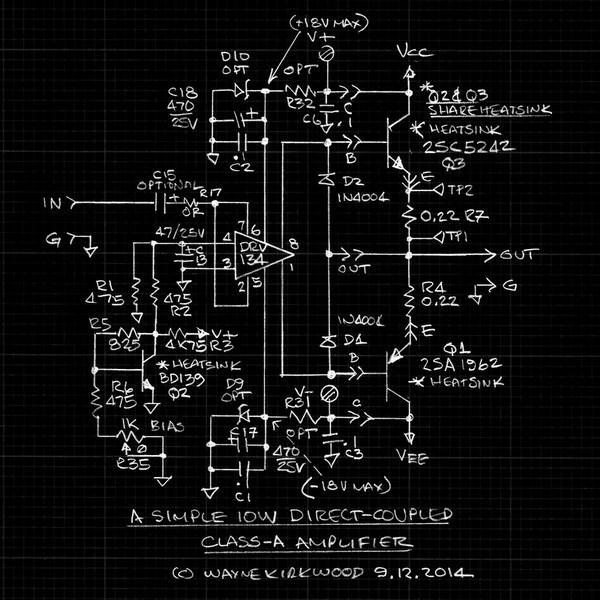
For a comparison I also measured the THD at the 10V peak level of the generic 35W amp. (6.25W 8 Ohm.)
It was about 0.25% THD, predominately third and without switching artifacts, versus the <0.04% THD of the class-A "heater" at the same power level.
At lower levels it dropped some, but not much, and there was a lot of noise in the residual.
0.25% at 1khz is pretty poor, at 20kHz not that unusual. If it is 0.25% at 1 kHz, and a conventional NF amp, it will likely be a lot worse at 20 kHz, or conversely 0.25% at 20kHz will generally clean up at 1kHz (where our hearing is more sensitive). While this is why I liked the two-tone IMD test because it stresses HF linearity, that can audibly sound like grundge (another technical term, but grunge has less HF content, more LF content than grit

).
By switching artifacts are you talking about crossover distortion (spikey looking in THD product)? Class G or H amps can have switching related artifacts when they change PS rails that couple back through the output device Miller capacitance, and I guess an amp with switching PS can have clock frequency noise in the distortion product too. (I suspect your 35W amp uses none of the above.)
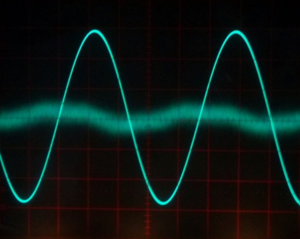
What was interesting was the clipping behavior of the class-A circuit.
To monitor the transfer function I put the input into CH-A and the output into CH-B of the 'scope and switched it to X-Y.
This displays linearity and clipping is very obvious due to the change in the line slope.
Until the clipping point the line is a razor sharp diagonal.
When it clips, the slope abruptly changes.
Since the clipping point with +/-18V supplies was a little too loud, I reduced the supply to force clipping.
What I heard was smoother than what I thought I would hear.
So there may be something about the "softness" of Class-A clipping compared to other amp classes.
It does round the waveform before it hits the wall.
Not to be more pedantic than normal, I suspect the clipping/OL behavior is dominated by the open loop output stage, not the class A bias. Class A amps can also use tons of NF and will then clip as suddenly as any other NF amp.
I like to characterize amp recovery from clipping, like how a race car handles after bumping the wall at speed. Important to race care drivers, not so much for careful drivers. At Peavey and in the sound reinforcement industry clipping power amps is more normal than not. That's why pretty much 100% of Peavey amps were designed with clip limiters that managed the behavior when overdriven to sound relatively benign (like a little extra compression).
Maybe it's the open loop output going Ohmic when saturated and not having feedback attempting to cope with overload.
Maybe it's not having the load part of the feedback network.
I really don't know.
I vote for door number 1, while prudent (amp) design anticipates clipping and engineers in fast recovery. One common technique used in power amps is to use anti-saturation clamp diodes in the driver transistors to prevent them from hard saturation. A saturated driver transistor charges up the base region, and this charge needs to be dissipated again before the transistor returns to normal operation. Clamping it to prevent saturation, allows near instantaneous recovery from clipping. Besides the driver stage any-where within the NF loop that loses the NF control when the output saturates can and will charge to some erroneous level, that it must again recover from after the clip event passes before the loop is stable again.
I suspect your front end is well behaved and recovers quickly from clipping, Your output stage not only goes ohmic, but probably is ohmic all the time. While that output behavior changes when one of the two output devices saturates. That might look like a 6dB gain drop between first output clipping and both clipping.
What I gather from this is that 10W/channel may be enough for these speakers and if really pushed into clipping won't sound that bad.
I can monitor at low, medium or high level without grit.
The only downside is that it takes 75W to get 20W.
This design looks interesting for low power and may even be a merchantable esoteric audio product, if you have the stomach to deal with those customers (I don't). I wonder if there is a way to reduce the low distortion even further by adding an AC signal component into the class A bias port. This class A tweak needs to be FW rectified to increase the class A current in both extremes... Of course it should sound fine as is, and the extra complexity will detract from it's elegance that such customers will embrace.
JR
Cancel the "cancel culture", do not support mob hatred.