A Simple 10W Direct-Coupled Class-A Power Amplifier
Posted: Wed Sep 10, 2014 3:24 pm
Introduction:
A few days ago I got the wild idea of trying the Dual Class-A headphone amp board to drive a pair of Minimus 7 near field monitors.
The link for the headphone amp project is here: viewtopic.php?f=7&t=509
With an 85 mA idle current and small heatsink I was pretty sure it would not be able to produce much power without distorting heavily.
I shorted the 33 Ohm build-out resistors normally used for 'phones and put some voltage gain ahead of the amp since its unity gain.
About 10V p-p (1.5W) into the 8 Ohm speakers was a good listening level; at 20V p-p (6.25W) it was as loud as I would want to monitor in the near field without fatigue.
The original acoustic suspension Minimus 7s turn out to be pretty efficient.
How did it sound?
Amazing.
Gone was the low-level grit I had grown accustomed to using 35W-Ch amps driving these efficient speakers at 5% to 18% of the amp's rated power.
It seemed brighter with more detail and better imaging even at low levels.
It made me want to box one up.
How did it measure?
It measured awful.
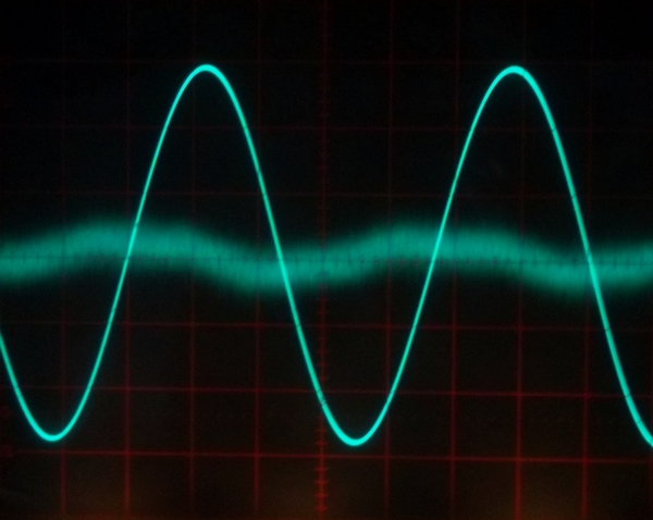
Really bad. At 6W about 1.6% THD.
At lower levels it measured outstanding.
All I needed was more idle current. Lots more.
So what to make of this?
I started doing some research on 10W class-A amps and found the work of JL Linsley Hood, Pass (Zen), Rod Elliot and others.
The references to those works are at the end of this post.
Elliot suggests that the optimum bias current for a Class-A is about 75%, or 0.75 X Iload-peak.
My little overstressed amp was running, at the 6W level at 8.5%, or 0.085 X Iload-peak.
10W into 8 Ohms is about 12.6V and 1.58A peak.
Iq should be in the range of 1.2A...
But it still sounded good. Hmmm....
Then a light switched on. I finally "got" class-A power amplification.
Generalizing, class-A amps have highest THD at maximum level.
Class A/B or Class B amps have their lowest THD typically just below the clipping point and rising THD with decreasing input level.
Duh. You can hear the difference.
The difference is in the detail.
Maybe the "golden ears" were right.
Taking it further:
I knew that a THD spec of 1.6% at 6W wouldn't fly.
The question then became "Could the Dual Class-A driver using the DRV134 be used to drive some really big output devices on monster heatsinks?"
The answer is yes!
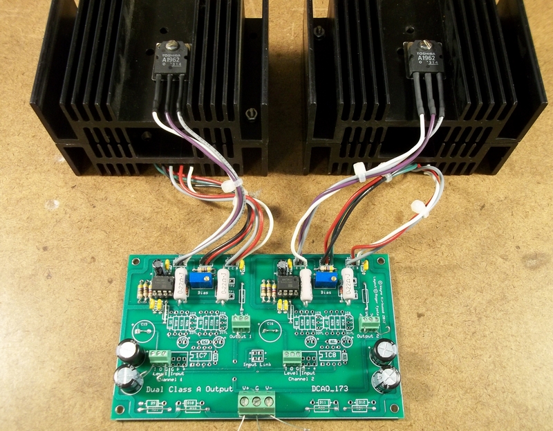
Dual 10W Class-A Amp Stuffing Single Channel
The emitter resistors are 0.22 Ohms It's really this simple to drive big external transistors.
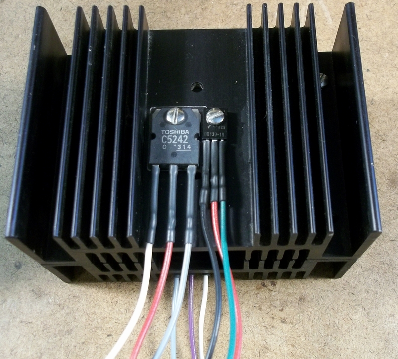
Dual 10W Class-A NPN Heatsink Single Channel
The 2SC5242 TO-3P device is the NPN Output. The BD139 is the Vbe multiplier and provides thermal feedback.
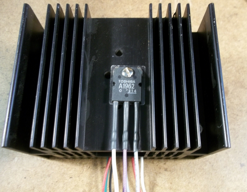
The 2SA1962 TO-3P device is the PNP Output.
Two random NPN/PNP device pairs had Vbe matching around 1 mV.
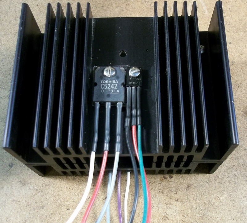
The two heatsinks are bolted back-to-back to form a stack and thermally couple the two pairs.
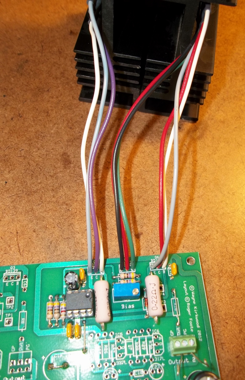
Flying leads from the heatsink stack connect to the Dual Class-A board.
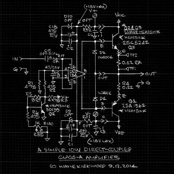
Schematic of a Simple 10W Direct-Coupled Class-A Power Amplifier Using a DRV134, 2SA1962 and 2SC5242.
The idle current for both channels is about 2.5A or 150W with +/-15V supplies.
The transistors run about 85 deg C.
On the prototype for use with a regulated bench supply I wired the collector leads directly back to the circuit board and made the power supply series resistors jumpers.
When I build it for use on the bench I may use a open-frame linear supply I already have.
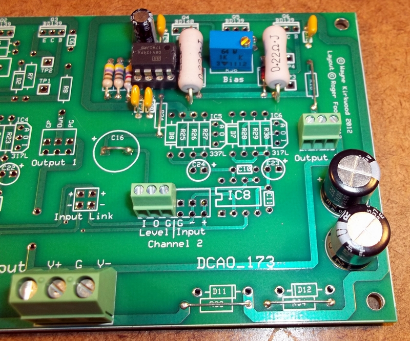
For unregulated power supplies, the collectors can be taken directly to the power supply and the DRV134 pre-driver supplied by Zener regulated shunts on-board or a regulated sub-supply.
(The 0.22 Ohm emitter ballast resistors can also be off-board if desired.)
The DRV134 should be operated at +/-18V maximum.
The power amp has about a 4V saturation voltage so a +/-13V peak output requires a +/-17V supply.
The circuit description for the Dual Class-A schematic shown above can be found in the headphone amp documents: viewtopic.php?f=7&t=509
How does it measure?
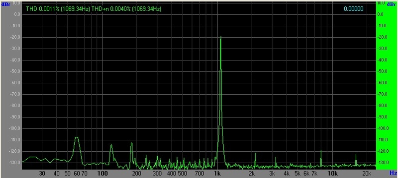
8 mW into 8 Ohms Iq 910 mA no analyzer attenuation
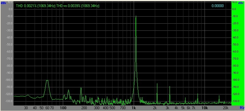
80 mW into 8 Ohms Iq 910 mA no analyzer attenuation
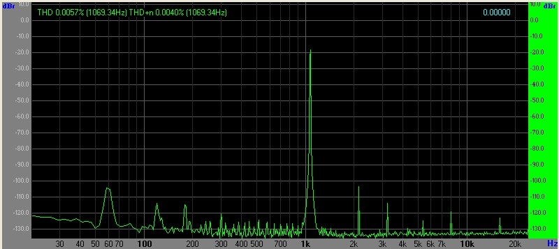
660 mW into 8 Ohms Iq 910 mA
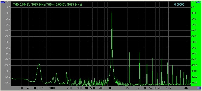
8W into 8 Ohms Iq 910 mA
A couple of notes:
For starters the Dual Class-A output runs open loop and the circuit is unity gain.
Negative feedback is local and internal to the DRV134.
Secondly, the design is fully DC-coupled and does not require servos.
The measured output offset was about 6 mV.
By comparison most other Class-A designs have overall negative feedback with about 23 dB of voltage gain.
Most power amps require the inputs to be attenuated to listen at low level with lot's of gain following the attenuation.
The Hood, Pass and Elliot design's outputs are AC-coupled to the load.
I need to wire up a second monster heatsink and listen to this now that I can get the idle current up.
I also have a design in process for an active Volume Control with Variable Width.
An active control coupled with a unity gain Class-A buffer stage does not require large amounts of gain to listen at low levels.
It does not force the listener into a less-than-optimum "attenuate then amplify" strategy.
Some interesting references:
AC-Coupled Class-A Designs
"Simple Class-A Amplifier," JL Linsley Hood, Wireless World, April 1969.
http://www.keith-snook.info/wireless-wo ... 20-%20.pdf
"The Zen Amplifier," Nelson Pass.
https://www.passdiy.com/download.php?do ... zenamp.pdf
"Death of Zen (DoZ) - A New Class-A Power Amp," Rod Elliott (ESP).
http://sound.westhost.com/project36.htm
Some Clever DC-Coupled Class-A Designs
"A10"
These designs are DC-coupled. The bias scheme in the second and third figures use a symmetrical diode bias.
In some ways it's similar to the "mirror" Vbe bias scheme but rather than use a single Vbe reference and it's inverted compliment, it uses two diodes.
Both DC and AC feedback in these circuits are taken from the output.
Thus, the output is closed loop.
http://www.mimave.net/chibidac/mdd2955.html
A few days ago I got the wild idea of trying the Dual Class-A headphone amp board to drive a pair of Minimus 7 near field monitors.
The link for the headphone amp project is here: viewtopic.php?f=7&t=509
With an 85 mA idle current and small heatsink I was pretty sure it would not be able to produce much power without distorting heavily.
I shorted the 33 Ohm build-out resistors normally used for 'phones and put some voltage gain ahead of the amp since its unity gain.
About 10V p-p (1.5W) into the 8 Ohm speakers was a good listening level; at 20V p-p (6.25W) it was as loud as I would want to monitor in the near field without fatigue.
The original acoustic suspension Minimus 7s turn out to be pretty efficient.
How did it sound?
Amazing.
Gone was the low-level grit I had grown accustomed to using 35W-Ch amps driving these efficient speakers at 5% to 18% of the amp's rated power.
It seemed brighter with more detail and better imaging even at low levels.
It made me want to box one up.
How did it measure?
It measured awful.
Really bad. At 6W about 1.6% THD.
At lower levels it measured outstanding.
All I needed was more idle current. Lots more.
So what to make of this?
I started doing some research on 10W class-A amps and found the work of JL Linsley Hood, Pass (Zen), Rod Elliot and others.
The references to those works are at the end of this post.
Elliot suggests that the optimum bias current for a Class-A is about 75%, or 0.75 X Iload-peak.
My little overstressed amp was running, at the 6W level at 8.5%, or 0.085 X Iload-peak.
10W into 8 Ohms is about 12.6V and 1.58A peak.
Iq should be in the range of 1.2A...
But it still sounded good. Hmmm....
Then a light switched on. I finally "got" class-A power amplification.
Generalizing, class-A amps have highest THD at maximum level.
Class A/B or Class B amps have their lowest THD typically just below the clipping point and rising THD with decreasing input level.
Duh. You can hear the difference.
The difference is in the detail.
Maybe the "golden ears" were right.
Taking it further:
I knew that a THD spec of 1.6% at 6W wouldn't fly.
The question then became "Could the Dual Class-A driver using the DRV134 be used to drive some really big output devices on monster heatsinks?"
The answer is yes!
Dual 10W Class-A Amp Stuffing Single Channel
The emitter resistors are 0.22 Ohms It's really this simple to drive big external transistors.
Dual 10W Class-A NPN Heatsink Single Channel
The 2SC5242 TO-3P device is the NPN Output. The BD139 is the Vbe multiplier and provides thermal feedback.
The 2SA1962 TO-3P device is the PNP Output.
Two random NPN/PNP device pairs had Vbe matching around 1 mV.
The two heatsinks are bolted back-to-back to form a stack and thermally couple the two pairs.
Flying leads from the heatsink stack connect to the Dual Class-A board.
Schematic of a Simple 10W Direct-Coupled Class-A Power Amplifier Using a DRV134, 2SA1962 and 2SC5242.
The idle current for both channels is about 2.5A or 150W with +/-15V supplies.
The transistors run about 85 deg C.
On the prototype for use with a regulated bench supply I wired the collector leads directly back to the circuit board and made the power supply series resistors jumpers.
When I build it for use on the bench I may use a open-frame linear supply I already have.
For unregulated power supplies, the collectors can be taken directly to the power supply and the DRV134 pre-driver supplied by Zener regulated shunts on-board or a regulated sub-supply.
(The 0.22 Ohm emitter ballast resistors can also be off-board if desired.)
The DRV134 should be operated at +/-18V maximum.
The power amp has about a 4V saturation voltage so a +/-13V peak output requires a +/-17V supply.
The circuit description for the Dual Class-A schematic shown above can be found in the headphone amp documents: viewtopic.php?f=7&t=509
How does it measure?
8 mW into 8 Ohms Iq 910 mA no analyzer attenuation
80 mW into 8 Ohms Iq 910 mA no analyzer attenuation
660 mW into 8 Ohms Iq 910 mA
8W into 8 Ohms Iq 910 mA
A couple of notes:
For starters the Dual Class-A output runs open loop and the circuit is unity gain.
Negative feedback is local and internal to the DRV134.
Secondly, the design is fully DC-coupled and does not require servos.
The measured output offset was about 6 mV.
By comparison most other Class-A designs have overall negative feedback with about 23 dB of voltage gain.
Most power amps require the inputs to be attenuated to listen at low level with lot's of gain following the attenuation.
The Hood, Pass and Elliot design's outputs are AC-coupled to the load.
I need to wire up a second monster heatsink and listen to this now that I can get the idle current up.
I also have a design in process for an active Volume Control with Variable Width.
An active control coupled with a unity gain Class-A buffer stage does not require large amounts of gain to listen at low levels.
It does not force the listener into a less-than-optimum "attenuate then amplify" strategy.
Some interesting references:
AC-Coupled Class-A Designs
"Simple Class-A Amplifier," JL Linsley Hood, Wireless World, April 1969.
http://www.keith-snook.info/wireless-wo ... 20-%20.pdf
"The Zen Amplifier," Nelson Pass.
https://www.passdiy.com/download.php?do ... zenamp.pdf
"Death of Zen (DoZ) - A New Class-A Power Amp," Rod Elliott (ESP).
http://sound.westhost.com/project36.htm
Some Clever DC-Coupled Class-A Designs
"A10"
These designs are DC-coupled. The bias scheme in the second and third figures use a symmetrical diode bias.
In some ways it's similar to the "mirror" Vbe bias scheme but rather than use a single Vbe reference and it's inverted compliment, it uses two diodes.
Both DC and AC feedback in these circuits are taken from the output.
Thus, the output is closed loop.
http://www.mimave.net/chibidac/mdd2955.html