
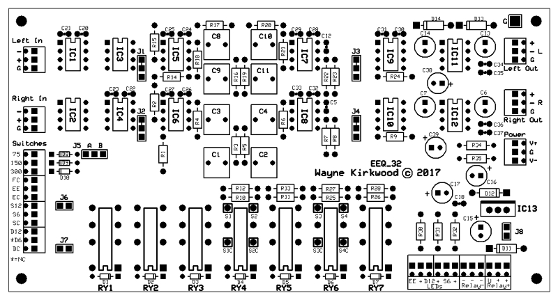
I haven't done the layout yet.
The design will have optional on-board Mid Side encoding/decoding which can be jumper-bypassed if the signal is already MS encoded.
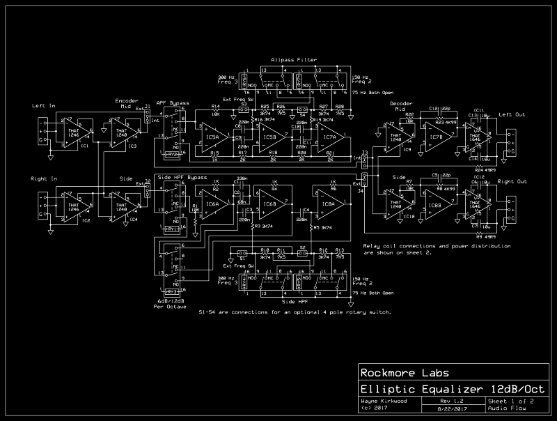
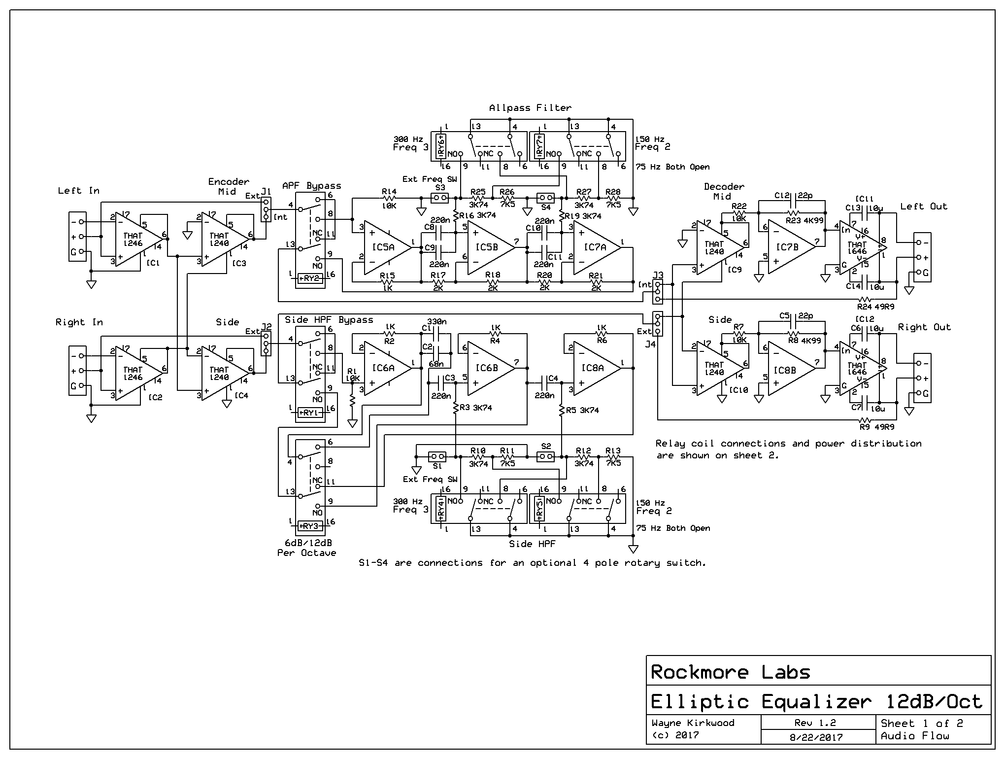
A Second-Order 12 dB/Octave Elliptic Equalizer with Allpass Delay Correction in Mid.
Larger image: https://www.proaudiodesignforum.com/ima ... heet_1.png
Circuit Description
IC1 and IC2 provide balanced inputs for the MS encoder formed by IC3 and IC4.
J1 and J2 bypass the MS encoder to accept external single-ended inputs which are already MS encoded.
The external MS configuration is useful when the EE is incorporated into an existing MS PC board at insert point F: viewtopic.php?f=7&t=262#p2918
Using an existing MS board provides the advantage of having the existing MS inserts ahead of the EE and one less MS encode/decode.
The EE is bypassed "hardwire" by RY1 and RY2.
Side High Pass Filter
Op amps A, B and C provide a single-order or second order high pass filter for the Side channel.
RY3 switches the filter from 12 dB/octave to 6 dB/octave.
Op amp A is a unity-gain voltage follower to buffer the filter input.
Maintaining precise unity gain within the filter passband is important to maintaining separation.
Very small gain errors cause very large changes in crosstalk above the EE frequency.
R1 provides bias for op amp A.
R2, and similar resistors R4, R6 and R14 limit inverting input current for NPN op amps such as the NE5532 or LME49720 that have back-to-back input protection diodes.
With some op amp types these may be reduced to 0Ω and with others having them in place can also provide some distortion cancellation.
With the NE5532, NJM2114 or LME40720 they are essential to prevent latch-up.
Op amp B is the first stage high pass filter for the Side channel.
For second-order EE filtering the HP network is provided by C3 and R3 plus R10 and R11.
When the EE is switched to single-order, the parallel combination of C1||C2 in series with C3 shift the cutoff frequency.
Op amp C and associated components provide a second, cascaded first order stage.
Side Filter Tuning
The filter frequencies can be tuned with either on-board relays or an external 4 pole switch.
In most cases three EE frequencies selected by relays is sufficient.
Four pole switches can be very costly: A 24 position 4 pole Goldpoint/Elma V24C, unwired, is about $191 US. http://goldpt.com/prices.html
Twelve position switches are similarly-priced. Six positions drops the cost to about $122 US.
Rather than use simpler single op amp second-order filters that would have unequal resistor values on each switch deck, a decision was made to use simpler cascaded single-order filters with all four poles of the switch having identical resistor values.
Two simple 6 dB/octave filters are cascaded to form a 12 dB/octave filter.
The EE frequency of the second-order filter is 1.56 times the cutoff of each single-order section.
Each stage of the 75 Hz filter will have an Fc that is 48 Hz. The 150 Hz Fc is 96 Hz; 300 Hz Fc is 192 Hz.
R3 and R5 limit the maximum frequency.
RY4 and RY5 switch the filter frequency by adding R10-R13 to step the frequency from 75 Hz to 150 and 300 Hz.
When stepped switches are used R10-13and RY4-7 are not installed.
Headers S1A-S1D provide a switch tie point.
DC bias current must be maintained through the off-board resistor string.
The switch common should ground the unused resistors to change tuning.
When the Side filter is set to 6 dB/octave the parallel combination of C1 and C2 are switched in by RY3.
When C1 and C2 in parallel are in series with C3, the effective capacitance is 0.14 uF.
The shifts the cutoff frequency to the actual 75, 150 or 300 Hz.
Mid Allpass Correction Filter
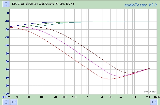
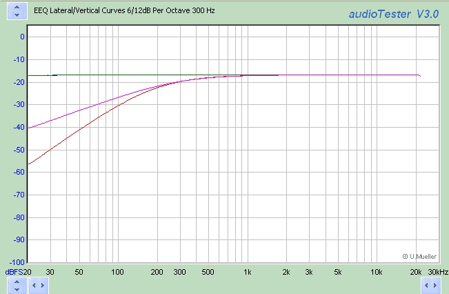
An allpass filter is used to match the phase response of the Side filter to achieve true second-order response of the crosstalk curve and eliminate uncorrected response peaking. (See earlier posts for various response curves.)
Op amp E is a unity gain voltage follower similar to op amp A that is used to buffer the allpass filter input.
Op amps F and G are allpass filter sections tuned identically to the second-order Side filter.
To match the phase response of the Side filter C8+C9 (or C10+C11) must be twice the value of C3 and C4.
RY6 and RY7 switch the allpass filter frequency using an identical resistive and relay network to the Side HP filter.
MS Decoder
The filtered outputs, which are in MS format, are decoded by IC8 and IC9.
MS decoded produces 2L and 2R outputs.
Op amps D and H attenuate the MS decoder to provide unity gain operation.
THAT1646 line drivers buffer the decoded L and R outputs.
Note that the 1646 output polarities are redefined to correct the inversion of op amps D and H.
When the MS decoder is not needed, J3 and J4 can be jumpered to bypass it.
When J3/J4 are used to link the filter outputs to an external MS decoder the THAT1646s must not be installed.
Bypass
RY1 bypasses the Side filter.
RY2 bypasses the Mid allpass filter.
RY3 switches the Side filter output from the second-order output to the first filter stage.
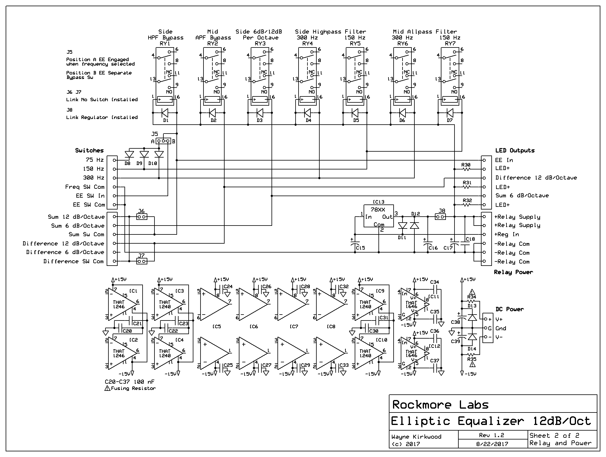
Relay Coil Wiring

A Second-Order 12 dB/Octave Elliptic Equalizer with Allpass Delay Correction in Mid. Sheet 2. Relay Coil Wiring.
Larger image: https://www.proaudiodesignforum.com/ima ... heet_2.png
I've tried to design a lot of flexibility into the EE's relay switching to permit a lot of front panel options and the ability to optionally switch it to 6 dB/octave.
If the Elliptic EQ is only going to be used at 12 dB/octave RY3 does not need to be installed and can be jumpered in the normally-closed position.
C1 and C2 can also be eliminated.
J5 provides a bypass option when the frequency relays are used.
When in the "A" position, connecting any Frequency control line to relay common will automatically engage the EE filter.
This configuration permits a single pole 3 or 4 position switch to act as both frequency select and bypass.
When a three position switch is used a bypass switch for A/B comparison can be in series with the common.
A four position switch could also be used to provide Off-75-150-300 Hz positions.
When J5 is in the "B" position a separate bypass pushbutton can be used to activate the EE.
If an external rotary switch is used to set the EE frequency J5 should be in the "B" position.
The second block of switch connections, labeled "Sum" and "Difference" are optional SPDT switch connections to alter filter slopes to 6 dB/octave.
If these are not used J6 and J7 are installed.
If a stepped frequency switch is used RY4-RY7 are not installed.
Relay Power and Indicators
The EE will have LED outputs to show actuation of RY1, RY2 and RY3.
Resistors R30-R33 provide current limiting.
When the EE is configured to operate at only 12 dB/octave only the "EE In" LED is used.
If switches are installed to permit 6 dB/octave operation the Difference and Sum LED outputs may be useful.
Relay power for the EE is galvanically-isolated on the board from audio ground.
External coil power may be unregulated or regulated.
The on-board 24V regulator has a separate input connection.
Jumper J8 connects the 7824 regulator to the Relay Supply connection.
When the on-board regulator is used the relay supply connections become 24V outputs.


