THAT2252 RMS Detector Replacement Using A THAT300 Array

Where we discuss new analog design ideas for Pro Audio and modern spins on vintage ones.
User avatar
mediatechnology
Posts: 5458
Joined: Sat Aug 11, 2007 2:34 pm
Location: Oak Cliff, Texas
Contact:

Re: THAT2252 RMS Detector Replacement Using A THAT300 Array

Post by mediatechnology »

Gary Hebert of THAT sent me a variation of the current rectifier which uses Q2 to pre-bias the rectifier in class A-B similar to the THAT2252.
Gary liked JR's common base stage, Q9.


Image
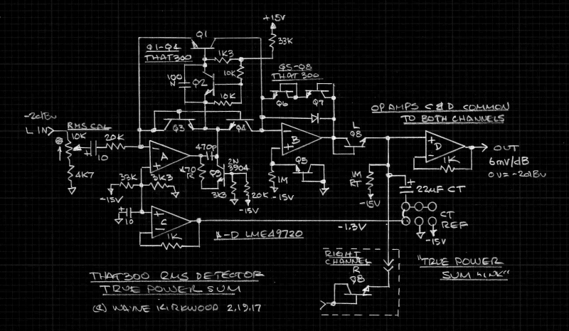
THAT2252 replacement using THAT300 and current rectification with class A-B bias optimized for True Power Summing.

Current rectification is performed by op amp A, Q1-Q4 and Q9. (See also: viewtopic.php?f=6&t=856&start=16)
Q3 rectifies positive inputs. Q4 mirrors the current in diode-connected Q3.
Q2 provides class A-B bias for transistor Q1.
Q1 rectifies negative inputs.
Q1's collector current is a nearly-identical copy of the negative input current.
The collectors of Q1 and Q4 are combined to provide an output current equal to the absolute value of the input current.

The absolute value current output feeds the log converter at the inverting input of op amp B.
This particular log stage level-shifts the input to the converter, using Q5, so that the emitter of Q8 sets around 0V.
The THAT4305, 4315 and 4320 RMS detectors have a similar level shift.
This reduces temperature sensitivity when the detector output is combined with another channel for True Power Summing.

Since the timing capacitor (Ct) can now see either polarity I added op amp C to bias the -Ct terminal to below ground.
For polar electrolytic capacitors the -300 mV may not be significant and Ct- could be grounded.
Film timing caps could also be grounded.

Tantalum capacitors, which have tighter tolerance and lower DA excel as a Ct.
Tantalums prefer that the Ct- terminal be either biased negative by op amp C or tied to the -15V rail to avoid any reverse-polarity.
(A non-polarized Ct could also be made from two back-to-back capacitors. In the case of tantalums this is more expensive than op amp C.)
If Ct- is tied to the negative supply it is subject to supply noise and should also be rated at >16V.

The return current through Ct- is quite large and limited by op amp B's output current.
When Ct is grounded the return trace should be large.

Q8's dynamic impedance isolates op amp B's output from the large capacitive load of Ct.
When Ct- is referenced to op amp C's output it is also isolated from Ct's capacitive load by Q8.

When Ct- is connected to the -1.3V reference Ct's charging current is isolated from ground and returns to the supply rails.
Another advantage is that low-voltage tantalums can be used.

In this configuration a stereo True Power Sum detector uses 4 THAT300, and 3 LME49720 vs. 3 THAT300 and 3 LME49720 in the previous example.
User avatar
JR.
Posts: 3709
Joined: Sat May 24, 2008 7:21 pm
Contact:

Re: THAT2252 RMS Detector Replacement Using A THAT300 Array

Post by JR. »

mediatechnology wrote:

Tantalum capacitors, which have tighter tolerance and lower DA excel as a Ct.
A minor quibble, tantalum caps are actually known for relatively inferior DA. One reference I found suggest Silver mica, glass, and tantalum range from 1% to 5% DA. This is better than common (aluminum?) electrolytic caps at 10%, but polyester is more like 0.5% DA and my favorite dielectric polystyrene is as low as 0.002% DA.

It might be interesting to see if modern low impedance electrolytics are better for DA too, probably are since the mechanism is caused by distributed RxC so lower R should be better.

I've told this story before but back when I designed my CX record NR decoder kit, I noticed that Urie used a tantalum cap in an important att/release time-constant circuit. To afford similar response characteristics (DA actually matters for time-constant circuits that are charged and discharged through different impedances) I used a tantalum cap in my kit at that same circuit position.

JR
Cancel the "cancel culture", do not support mob hatred.
User avatar
mediatechnology
Posts: 5458
Joined: Sat Aug 11, 2007 2:34 pm
Location: Oak Cliff, Texas
Contact:

Re: THAT2252 RMS Detector Replacement Using A THAT300 Array

Post by mediatechnology »

Tantalum capacitors, which have tighter tolerance and lower DA excel as a Ct.
...compared to the commonly-used electrolytic timing cap.

My thinking is that a 22uF film (or a pair of 10 uF films) would be the ultimate timing capacitor. (And would be impressively big.)
User avatar
JR.
Posts: 3709
Joined: Sat May 24, 2008 7:21 pm
Contact:

Re: THAT2252 RMS Detector Replacement Using A THAT300 Array

Post by JR. »

mediatechnology wrote:
Tantalum capacitors, which have tighter tolerance and lower DA excel as a Ct.
...compared to the commonly-used electrolytic timing cap.

My thinking is that a 22uF film (or a pair of 10 uF films) would be the ultimate timing capacitor. (And would be impressively big.)
Back in the '70s I used a 22uF cap in a RIAA gain leg so it was working pretty hard (360 ohm IIRC).

I substituted a tantalum for the aluminum in that preamp and measured dramatically less phase shift at 20kHz. In my judgement dominated by the lower ESL/ESR.

I apologize for giving you homework, but I couldn't find a DA spec for low Z aluminum.

I suspect a crude null test between a tantalum and low Z aluminum when charged and discharged through different impedances. In fact the perfect test would be two identical circuits (Q8, Rt and Ct) but one using tantalum and the other low Z aluminum. This circuit could be used to prove the benefit of tantalum over high Z aluminum (if they still make them).

Sorry.. again.. just me being me. The audible consequence of this is pretty subtle and more important for encode/decode tracking in say a NR circuit than for single ended dynamic processing use.

JR
Cancel the "cancel culture", do not support mob hatred.
User avatar
mediatechnology
Posts: 5458
Joined: Sat Aug 11, 2007 2:34 pm
Location: Oak Cliff, Texas
Contact:

Re: THAT2252 RMS Detector Replacement Using A THAT300 Array

Post by mediatechnology »

I was able to check the DF not the DA.

A Nichicon 22 uF UVR electrolytic measured 0.19 DF; a 22 uF tantalum 0.03 DF.

I was going to use a film capacitor anyway in my build.
User avatar
JR.
Posts: 3709
Joined: Sat May 24, 2008 7:21 pm
Contact:

Re: THAT2252 RMS Detector Replacement Using A THAT300 Array

Post by JR. »

Yup film caps are betta...

JR
Cancel the "cancel culture", do not support mob hatred.
Hans
Posts: 73
Joined: Fri Jun 24, 2016 8:48 am

Re: THAT2252 RMS Detector Replacement Using A THAT300 Array

Post by Hans »

Has anyone ever looked at this VU meter topology.
It uses a complete different way to achieve a log conversion.

http://www.naun.org/main/NAUN/mcs/17-130.pdf

Hans
User avatar
mediatechnology
Posts: 5458
Joined: Sat Aug 11, 2007 2:34 pm
Location: Oak Cliff, Texas
Contact:

Re: THAT2252 RMS Detector Replacement Using A THAT300 Array

Post by mediatechnology »

Hans - Thank you for posting that link. It's a clever circuit.
User avatar
JR.
Posts: 3709
Joined: Sat May 24, 2008 7:21 pm
Contact:

Re: THAT2252 RMS Detector Replacement Using A THAT300 Array

Post by JR. »

Hans wrote:Has anyone ever looked at this VU meter topology.
It uses a complete different way to achieve a log conversion.

http://www.naun.org/main/NAUN/mcs/17-130.pdf

Hans
I didn't read that paper closely but it looks like a variant on something I did back in the late '70s-early '80s. I made a prototype 100 segment dB meter (actually displayed peak and VU simultaneously). I used the logarithmic discharge curve of a simple RC (e^-t/RC) to convert a FW rectified DC to dBu. Instead of generating a linear current (via PWM) wrt dB output I compared the rectified DC voltage to the RC discharge curve voltage and used that comparator output to gate a clock feeding a digital counter to generate a digital 100 tick (dB) count representing dB below FS.

I did this twice, once for the peak level and again for the average (VU) level. As I recall I alternated conversion between extracting the average dB that I displayed as a solid bar, and the peak dB that I displayed as a single segment. The fluorescent display was multiplexed internally as an array of 10x10, so I multiplexed between displaying the single segment (peak), the full all-ten segment blocks, and the partial (<10) segment to finish the average display. I probably multiplexed the display 4 ways so likely had one all-off period between the three active display periods. The persistence of the fluorescent gave a solid appearing display.

The company I designed this for fell on financial problems so I never built more than that one prototype and lost that one physical unit in a bankruptcy auction. I regret that no formal schematic survived or ever existed beyond my design notes.

I will not swear to the accuracy of this approach over the full 100 dB display range, but it was solid enough for the top 50-60 dB and made a pretty flashing light display down to the noise floor.

======
FWIW around the same time period I used a completely different circuit approach to make a dB to digital count. Inside the TS-1 I designed in the early '80s (schematic around here somewhere) I performed the log conversion more conventionally using transistor Vbe junctions to extract a linear +/- dB voltage, that I then converted that voltage to a current to feed a saw tooth integrator, and counted the number of times the sawtooth ramp reset over a fixed unit time. Positive dB or negative dB slewed in opposite directions.

I am not completely sure why I used two completely different approaches but I expect the TS-1 to be the more accurate of the two (it was test equipment after all). The TS-1 approach had worst errors at high dB (fraction of a dB high) due to Rbb in the logging transistor causing an error term. The RC approach was likely worst at very low level, while both required extra attention to the rectifier for low level high frequency as we've talked about before. IIRC I scratched out a first order solution for the Rbb error term but that never made it to production in the TS-1.

JR
Cancel the "cancel culture", do not support mob hatred.
User avatar
mediatechnology
Posts: 5458
Joined: Sat Aug 11, 2007 2:34 pm
Location: Oak Cliff, Texas
Contact:

Size Matters

Post by mediatechnology »

Yup film caps are betta...
Well, this will sure look impressive on the board:

Image

At $4 each I'm glad only one is required for True Power Summing.
Post Reply