I didn't build the shunt regulators and may modify it to provide a balanced output.
Using the shunt regulators it looks like the output ground is quasi-floating from the supply ground.
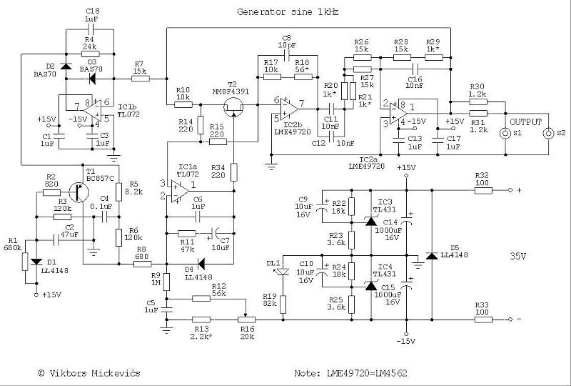
Viktors Mickevics Ultra Low Distortion Oscillator 1kHz
The PCM4222 EVM and oscillator combined measure 2 ppm distortion.
Thanks mediatechnology for the confirmation. yes the analog ones are placed fine and the AES of wrongly placed. i wasnt sure if i was missing a bracket.
I wonder have you used separate external regulators 3.3v and 4v on your pcb? or just used the on board regs?
is it possible to improve sound by doing this or is it just more reliable to use external regulators?
It occurred to me that you could leave the existing AES connectors and tack-solder flying leads to a panel-mounted one. I've never used the second AES port.
thanks for your reply. yes good idea, although i am right out of space in the box. i would need to reshuffle some parts. I hoped it would just slot in as the PDF states "chassis mounted for AES j7 j9"
i am in communication with TI so hopefully they will email something interesting.
i shall eventually find out about the benefits of the external regulators and so shall post that info here, just in case you find it interesting too.
There must be a good reason for TI to go to all the trouble to allow us the option. Hopefully improved sound, lower noise? But I suppose it could just be stability.
TI have informed me that the EVM was never meant to be chassis mounted.
Although the pdf seemed to indicate one could have a shielded and secure environment to test.
" The PCM4222EVM provides a complete environment for evaluating the functionality and performance of the PCM4222
integrated circuit." "J7 J9 = neutrik 3-Pin Male XLR Chassis Connector, Horizontal PC Mount."
Engineer says a de-soldering tool is required to remove the chassis AES before mounting as the wrong footprint has been used to chassis mount.
and will consider updating the PDF in next edition.
So it seems soldering wires underneath to a new neutrik chassis connector might be the best option. rather than risk de-soldering the XLRs.
I managed to get the PCM4222evm working, I had some DC offset issues only if the EVM high pass filter was not turned on.
test 1
computer> RME balanced >> EVM AES >> RME AES/computer = No problem. ( even with the EVM HPF switched off) very low noise
test 2 (same as before but insert an external soundcraft preamp)
computer> RME balanced >> balanced preamp unbalanced out >> EVM AES >> RME AES/computer = high DC offset (but not if the PCM4222EVM has its HPF set to on.
test 3 held held media player
android phone unbalance out >> EVM AES >> RME AES/computer = high DC when the phone was in pause/stand by, but not when playing a track.
With the hpf on the EVM the DC offset went away in all cases.
has anyone else noticed DC offset issues with the HPF off? is this normal with sending unbalanced to the EVM?
it just seems strange test 1 was o.k. but not the others.
The balanced inputs of the PCM4222EVM sit at the A/D Vcm voltage because it is not AC-coupled.
You really want some electrolytics in series with tip and ring. There are spots on the board for SMT caps you can solder TH components to.
If the device driving the EVM are AC-coupled but have large value pull-down resistors a hefty DC offset will develop.
If the device driving the EVM are DC-coupled op amp outputs with small 47R-ish build-out resistors there will be a small amount of offset and the op amp will sink the EVM's input current.