
I really liked polystyrene.... somewhere I had some 0.1uF polystyrenes that as fat as my thumb.
JR
Super Low Distortion Ultra Pure Audio Oscillators Revisited
Re: Super Low Distortion Ultra Pure Audio Oscillators Revisited
Cancel the "cancel culture", do not support mob hatred.
-
mediatechnology

- Posts: 5457
- Joined: Sat Aug 11, 2007 2:34 pm
- Location: Oak Cliff, Texas
- Contact:
Re: Super Low Distortion Ultra Pure Audio Oscillators Revisited
I have your 8200 pF polystyrenes...
I need to keep both J1 and J2.
Though they may sim the same with 1 or 2 links I just noticed that for a balanced-only configuration, where there would only be a single 10 nF at C4 and a single VR, there would no longer be symmetry.
So the J1/J2 shunts need to remain split.

I need to keep both J1 and J2.
Though they may sim the same with 1 or 2 links I just noticed that for a balanced-only configuration, where there would only be a single 10 nF at C4 and a single VR, there would no longer be symmetry.
So the J1/J2 shunts need to remain split.

Re: Super Low Distortion Ultra Pure Audio Oscillators Revisited
I do not understand about J1 J2.
I see a balanced-only configuration as a underpopulated board, no J1 no J2 no VR2 but a strap, four caps become one.
I see a balanced-only configuration as a underpopulated board, no J1 no J2 no VR2 but a strap, four caps become one.
-
mediatechnology
- Posts: 5457
- Joined: Sat Aug 11, 2007 2:34 pm
- Location: Oak Cliff, Texas
- Contact:
Re: Super Low Distortion Ultra Pure Audio Oscillators Revisited
If the two hot sides of J1 and J2 get connected together because one J is eliminated, C4 is populated and C6 becomes a link, then the bottom side of VR2 connects directly to the node of R9/R10. (C3/C5 not populated and J open.)
J2's left-hand connection should instead go to the node formed at the center of C3/4/5/6.
J2 is only installed when Nacho is switchable.
J1/J3 then switch balanced/unbalanced allowing a DPST switch to be used.
If the board is built balanced only then neither J1/J2/J3 are installed and the bottom of VR2 doesn't get connected to R9/R10 through a linked C6 because J2 is open.
Make it like this:

Re: Super Low Distortion Ultra Pure Audio Oscillators Revisited
For the balanced only version, I would manage going from 4 caps to only one, by means of footprints to allow the cap to jump over the J1 node.
-
mediatechnology
- Posts: 5457
- Joined: Sat Aug 11, 2007 2:34 pm
- Location: Oak Cliff, Texas
- Contact:
Re: Super Low Distortion Ultra Pure Audio Oscillators Revisited
I could do a C4A or C4B with C4B jumping across the jumper to the R9/R10 node as you suggest.
-
fredbloggstwo
- Posts: 17
- Joined: Fri Feb 02, 2018 5:53 pm
Re: Super Low Distortion Ultra Pure Audio Oscillators Revisited
Hi folks,
Just been through this thread and it looks quite exciting.
I have a couple of questions though:
1 what would be involved in turning the oscillator into a switched full range device (20 to 20k)
2 if you are trying to get the most from a 5532/5534, have you seen the trick about using an external diff pair connected to the compensation pins on a 5534. It is in the dim and distant past of my memory, and I can't find my reference for it, but bypassing the 5534s front end allows one to drop the noise down quite a bit and get around those pesky input diodes if needed.
Cheers
Mike
Re: Super Low Distortion Ultra Pure Audio Oscillators Revisited
switches, more components, and probably a few tweaks. But Wayne is the man for this one.fredbloggstwo wrote: ↑Mon Feb 08, 2021 2:19 pm Hi folks,
Just been through this thread and it looks quite exciting.
I have a couple of questions though:
1 what would be involved in turning the oscillator into a switched full range device (20 to 20k)
you could probably find it and other similar circuits in a search right here.....2 if you are trying to get the most from a 5532/5534, have you seen the trick about using an external diff pair connected to the compensation pins on a 5534. It is in the dim and distant past of my memory, and I can't find my reference for it, but bypassing the 5534s front end allows one to drop the noise down quite a bit and get around those pesky input diodes if needed.
based on the results Wayne is getting why bother?Cheers
Mike
JR
Cancel the "cancel culture", do not support mob hatred.
-
mediatechnology
- Posts: 5457
- Joined: Sat Aug 11, 2007 2:34 pm
- Location: Oak Cliff, Texas
- Contact:
Re: Super Low Distortion Ultra Pure Audio Oscillators Revisited
Hi MIke!fredbloggstwo wrote: ↑Mon Feb 08, 2021 2:19 pm Hi folks,
Just been through this thread and it looks quite exciting.
I have a couple of questions though:
1 what would be involved in turning the oscillator into a switched full range device (20 to 20k)
2 if you are trying to get the most from a 5532/5534, have you seen the trick about using an external diff pair connected to the compensation pins on a 5534. It is in the dim and distant past of my memory, and I can't find my reference for it, but bypassing the 5534s front end allows one to drop the noise down quite a bit and get around those pesky input diodes if needed.
Cheers
Mike
Thanks for the post.
You'll find the info about the external diff pair to the compensation pins here: viewtopic.php?f=12&t=1135
The OP is for the FET example but there are BJT examples later in the thread.
My thought was to experiment with an optimized 100 Hz version and a 19/20 kHz resistively-summed pair and just switch the outputs.
The 19/20 kHz combo won't need a notch filter or ultra low THD since I will use it to look for IM at 1 kHz.
-
mediatechnology
- Posts: 5457
- Joined: Sat Aug 11, 2007 2:34 pm
- Location: Oak Cliff, Texas
- Contact:
Re: Super Low Distortion Ultra Pure Audio Oscillators Revisited
I've had to build over a dozen boards since I last worked on this project and I'm just getting back to laying out a board.
Today I'm loading the Protoboard back onto the workbench and will fire up the oscillator.
Probably about half the boards I lay out are motivated by wanting to get the Protoboards back.
The Input-capacitorless mic preamp fits into that category.
State-of-the-art advancement isn't necessarily the goal - cleaning up the bench is.
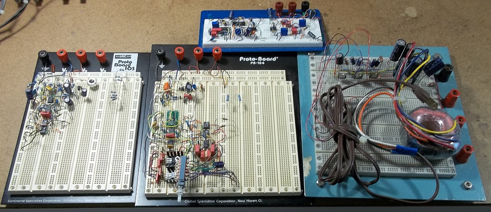
MC Phono Preamp, Input-capacitorless Mic Preamp and Power Supply, Super Low-Distortion Oscillator.
The MC preamp got a layout - the Ultra Low Distortion Oscillator and Input-capacitorless preamp are next on my hit list.
Not shown is the Nixie clock driver Protoboard which will be solely for my own amusement.
Beauty and the Beast: Some Protoboards Grow Up Beautiful, Others Don't viewtopic.php?f=6&t=1102&p=12659#p12659
Today I'm loading the Protoboard back onto the workbench and will fire up the oscillator.
Probably about half the boards I lay out are motivated by wanting to get the Protoboards back.
The Input-capacitorless mic preamp fits into that category.
State-of-the-art advancement isn't necessarily the goal - cleaning up the bench is.
MC Phono Preamp, Input-capacitorless Mic Preamp and Power Supply, Super Low-Distortion Oscillator.
The MC preamp got a layout - the Ultra Low Distortion Oscillator and Input-capacitorless preamp are next on my hit list.
Not shown is the Nixie clock driver Protoboard which will be solely for my own amusement.
Beauty and the Beast: Some Protoboards Grow Up Beautiful, Others Don't viewtopic.php?f=6&t=1102&p=12659#p12659