Re: Super Low Distortion Ultra Pure Audio Oscillators Revist
Posted: Mon May 22, 2017 11:55 am
I now have an AGC loop that I'm happy with based on an adaption of Vicktors Mickevics' design.
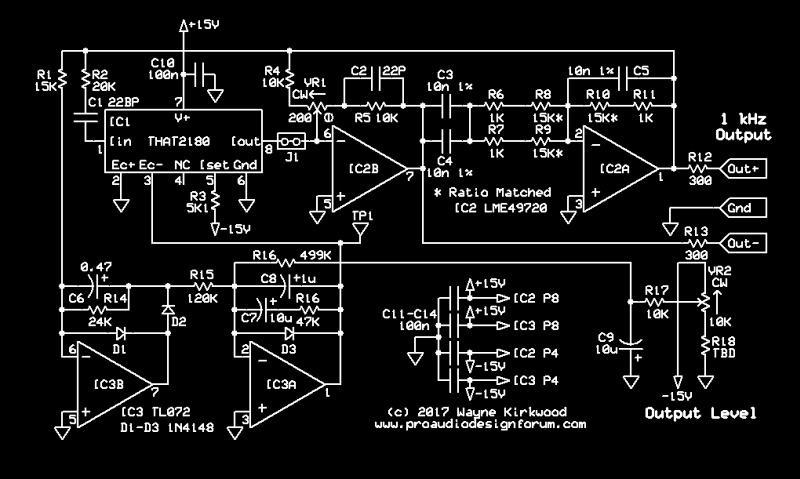
The updated Wien bridge portion of the oscillator has an added link to disconnect the VCA output for test.
I'm also using a different VCA Ec pin than before and increased the input resistor to 47KΩ.
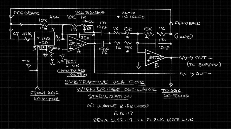
Subtractive VCA Stabilizes Wien Bridge Oscillator Rev A.
A link was added at the output of the VCA to allow the 1KΩ trim pot to be preset.
With the link open the pot is trimmed so the oscillator has enough gain to start.
(The 1K can be made much smaller in value maybe about 200Ω.)
With the link closed the final trim adjustment can be made by setting Ec- to +380 mV.
This sets the VCA Q-point to about -63dB attenuation.
The AGC is a modified version of Vicktors Mickevics' half-wave design.
I found that the heavy filtering of Vicktors' half-wave design had just as low a distortion as a full-wave rectifier.
Due to the way the VCA works the "kick-start" power-up circuit in his FET-based design is not needed.
The whole oscillator - excluding output buffers - is just two LME49720 and a THAT2180 VCA.
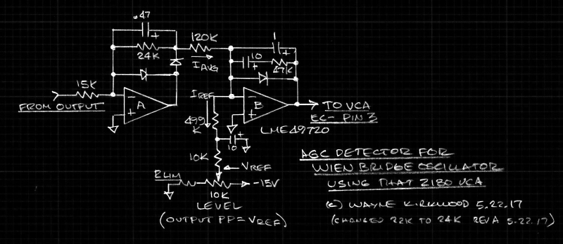
AGC Circuit for A Subtractive VCA_Stabilized Wien Bridge Oscillator.
Op amp A is a filtered half-wave rectifier which produces a positive output for negative-going inputs.
It has a gain of 1.6.
The output of the half-wave rectifier is converted to current by the 120KΩ resistor.
The AGC loop servo point is the inverting input of op amp B.
Current is pulled out of the summing node by the output level adjustment.
The oscillator output level is controlled by the servo action of op amp B and the VCA so that average current sourced from the rectifier vs. the reference current hold the two currents in equilibrium.
With the values shown, the oscillator output peak-to-peak level is approximately equal to the reference voltage at the wiper of the output level pot.
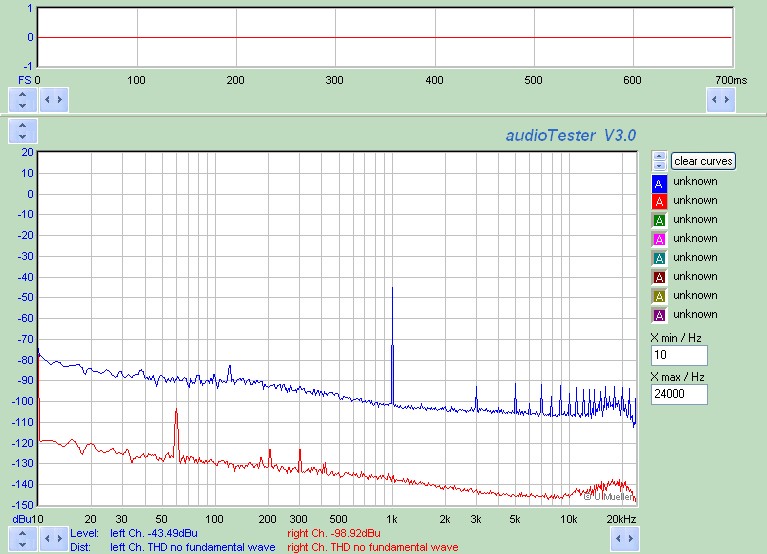
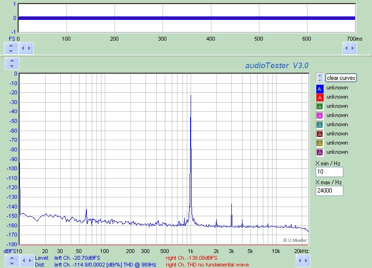
At this point I'm measuring converter distortion.
I need to build the notch filter.
The updated Wien bridge portion of the oscillator has an added link to disconnect the VCA output for test.
I'm also using a different VCA Ec pin than before and increased the input resistor to 47KΩ.
Subtractive VCA Stabilizes Wien Bridge Oscillator Rev A.
A link was added at the output of the VCA to allow the 1KΩ trim pot to be preset.
With the link open the pot is trimmed so the oscillator has enough gain to start.
(The 1K can be made much smaller in value maybe about 200Ω.)
With the link closed the final trim adjustment can be made by setting Ec- to +380 mV.
This sets the VCA Q-point to about -63dB attenuation.
The AGC is a modified version of Vicktors Mickevics' half-wave design.
I found that the heavy filtering of Vicktors' half-wave design had just as low a distortion as a full-wave rectifier.
Due to the way the VCA works the "kick-start" power-up circuit in his FET-based design is not needed.
The whole oscillator - excluding output buffers - is just two LME49720 and a THAT2180 VCA.
AGC Circuit for A Subtractive VCA_Stabilized Wien Bridge Oscillator.
Op amp A is a filtered half-wave rectifier which produces a positive output for negative-going inputs.
It has a gain of 1.6.
The output of the half-wave rectifier is converted to current by the 120KΩ resistor.
The AGC loop servo point is the inverting input of op amp B.
Current is pulled out of the summing node by the output level adjustment.
The oscillator output level is controlled by the servo action of op amp B and the VCA so that average current sourced from the rectifier vs. the reference current hold the two currents in equilibrium.
With the values shown, the oscillator output peak-to-peak level is approximately equal to the reference voltage at the wiper of the output level pot.
At this point I'm measuring converter distortion.
I need to build the notch filter.