Stereo Width Controller Construction Information
Posted: Tue Apr 14, 2015 11:44 am
This is the construction thread for the Stereo Width Controller PC board.
Stereo Width Controller PC Board: http://ka-electronics.com/shop/index.ph ... arch=width
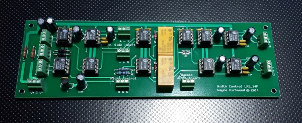
Stereo Width Controller PC Board
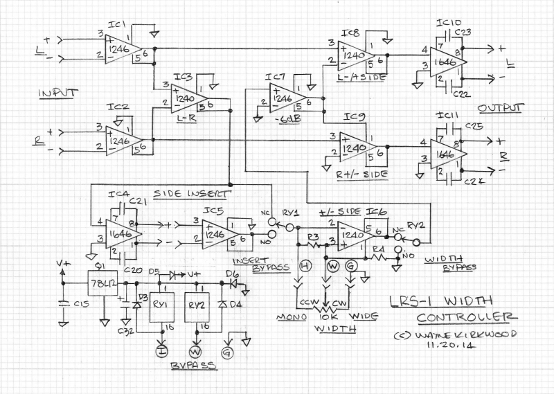
Stereo Width Controller Schematic
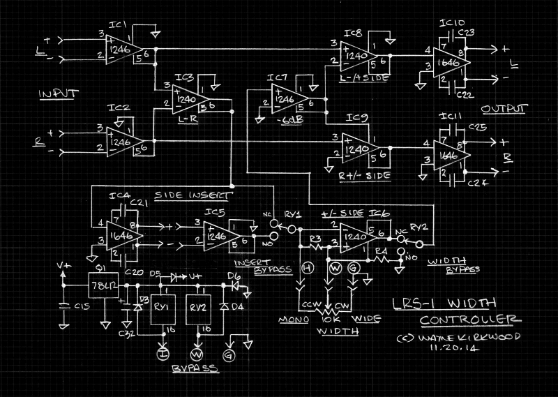
Stereo Width Controller Schematic
Assembly Instructions
Assembly instructions: http://www.ka-electronics.com/images/pd ... ctions.pdf
Schematic suitable for printing: http://www.ka-electronics.com/images/jp ... _small.jpg
Parts List and Bill of Materials
The Mouser Project Manager bill of materials for the Width Controller can be used to order directly from Mouser or used simply as a guide for components you source locally:
Note that the 10K linear taper pot is not included in the bill of materials.
Bill of Materials without THAT ICs: https://www.mouser.com/ProjectManager/P ... 96947b82d5
Bill of Materials with THAT ICs: https://www.mouser.com/ProjectManager/P ... c66b355bb9
Semiconductors
4) THAT1246 IC1, IC2, IC5, IC7
4) THAT1240 IC3, IC6, IC8, IC9
3) THAT1646 IC4, IC10, IC11
1) LM78L12 IC12
2) 1N4004 D1, D2
4) 1N4148
Electromechanical and Connectors
2) Relay DS2Y-S-DC12V RY1, RY2
11) 8 pin sockets
10) 3 pin Phoenix terminal blocks Mouser 651-1725669
Capacitors
15) 0.1/100V Mono Ceramic Mouser 581-SR201C104KAR C1-C15
6) 10uF radial NP or polarized 25V or greater C20-C25
1) 10uF radial polarized 25V or greater C32
2) 47uF/35V C30, C31
Resistors
2) 1R 1/4W R1, R2. (Flameproof/fusible is better but generic carbon film if that's all that's available. If you do use CF space it off the board.)
2) 100K 1% Mouser 271-100K-RC, R3, R4
PC Board Stuffing Guide:
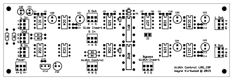
Stereo Width Controller PC Board Stuffing Guide
How it Works
The core circuitry of the LRS-1 Width controller is IC3, IC6, IC8 and IC9.
THAT1246 balanced line receivers along with THAT1646 outputs provide both buffering and balanced inputs and outputs.
Like any of the matrices using differential line receivers it is important that the driving source impedance is an op amp output.
If the source is not buffered, the source impedance becomes part of the matrix and degrades its accuracy.
The balanced inputs provide the low source impedance required by IC3, IC8 and IC9.
THAT1646 output stages provide L and R balanced outputs.
IC3, a THAT1240, provides a Side signal that is that is equal to (L-R).
(A 1246 was originally used for IC3 to provide the needed (L-R)/2 signal but to maintain signal level at the insert send a unity gain THAT1240 was used and attenuation added at IC7.)
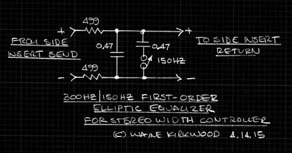
IC4 and IC5 provide an external Side Insert with RY1 providing bypass.
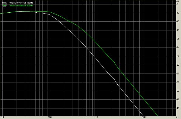
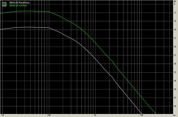
A low pass filter in the external Side Insert makes the circuit become an Elliptic Equalizer for vinyl mastering providing low frequency crossover to mono.
IC6, a THAT1240, along with a 10K linear potentiometer (or stepped switch) create a Side signal with a voltage gain, "k," that ranges from -1 to 0 to +1.
This permits Side to be subtracted or added to Left and Right.
100K resistors bridging the wiper of the pot to both ends of the pot provide bias current return for the THAT1240 input if the wiper lifts during rotation or switching.
If a stepped switch is used, Goldpoints are supplied in make-before-break and the 100K's can be removed to increase taper accuracy.
RY2 defeats the Width circuit for signal comparison.
IC7 attenuates the Side signal by a precise -6dB to provide a k{(L-R)/2} output.
THAT1240 summation stages IC8 and IC9 either add or subtract Side from Left and Right.
The Side signal at the output of IC7 is subtracted from L and added to R.
"Side" is evenly distributed between Left and Right but has opposite polarities.
Thus, Left contains a side component that is L + 0.5(side).
Right has a R -0.5(side) component.
If k=1 (IC6 is not inverting polarity) and the attenuation of IC7 is 0.5 then:
L = L +0.5(side) -0.5(side) = L
and
R = R -0.5(side) +0.5(side) = R.
Thus with no Side signal to make it stereo, L then equals R and the resulting signal is mono.
Obtaining mono is a subtractive process.
If k=0 then:
L= L +0.5 side
and R = R -0.5 side.
The result is normal stereo.
If k=-1 (IC6 is providing polarity inversion) and and the attenuation of IC7 is 0.5 then:
L = L +0.5(side) +0.5(side) = L + side
and
R = R -0.5(side) -0.5(side) = R - side.
Thus the amount of side in left and right are doubled relative to normal stereo where the side terms are +0.5 and -0.5.
Expanding width, or the side component, is an additive process.
The X-Y diagrams below show how the diagonal side axis is either fully collapsed to produce mono or doubled in width relative to normal stereo to expand width.
The following are X-Y Oscilloscope photos with 1 kHz applied to the Left channel and 10 kHz applied to the right.
When the polarity flipper's output is 0V, the Left/Right inputs are unprocessed and provide a "normal" stereo image.

A Stereo Width Control Using the +/-S Method, 1 kHz Left, 10 kHz Right, Set for Mono.
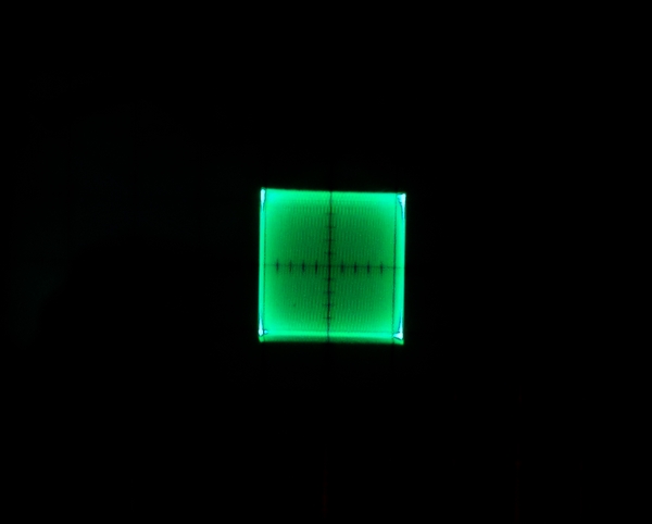
A Stereo Width Control Using the +/-S Method, 1 kHz Left, 10 kHz Right, Set for Stereo.
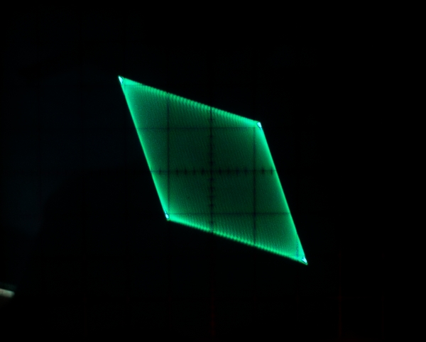
A Stereo Width Control Using the +/-S Method, 1 kHz Left, 10 kHz Right, Set for Wide.
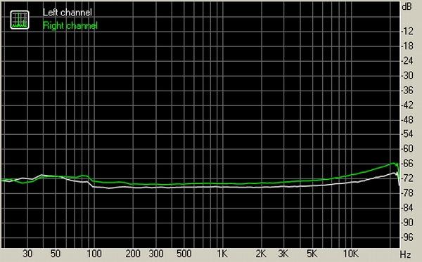
With the Width control centered crosstalk is excellent.
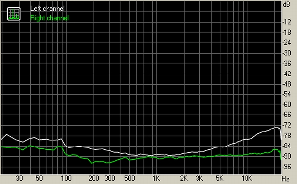
With the Width control bypassed, crosstalk is essentially that of the sound card used to perform the measurement.
Stereo Width Controller PC Board: http://ka-electronics.com/shop/index.ph ... arch=width
Stereo Width Controller PC Board
Stereo Width Controller Schematic
Stereo Width Controller Schematic
Assembly Instructions
Assembly instructions: http://www.ka-electronics.com/images/pd ... ctions.pdf
Schematic suitable for printing: http://www.ka-electronics.com/images/jp ... _small.jpg
Parts List and Bill of Materials
The Mouser Project Manager bill of materials for the Width Controller can be used to order directly from Mouser or used simply as a guide for components you source locally:
Note that the 10K linear taper pot is not included in the bill of materials.
Bill of Materials without THAT ICs: https://www.mouser.com/ProjectManager/P ... 96947b82d5
Bill of Materials with THAT ICs: https://www.mouser.com/ProjectManager/P ... c66b355bb9
Semiconductors
4) THAT1246 IC1, IC2, IC5, IC7
4) THAT1240 IC3, IC6, IC8, IC9
3) THAT1646 IC4, IC10, IC11
1) LM78L12 IC12
2) 1N4004 D1, D2
4) 1N4148
Electromechanical and Connectors
2) Relay DS2Y-S-DC12V RY1, RY2
11) 8 pin sockets
10) 3 pin Phoenix terminal blocks Mouser 651-1725669
Capacitors
15) 0.1/100V Mono Ceramic Mouser 581-SR201C104KAR C1-C15
6) 10uF radial NP or polarized 25V or greater C20-C25
1) 10uF radial polarized 25V or greater C32
2) 47uF/35V C30, C31
Resistors
2) 1R 1/4W R1, R2. (Flameproof/fusible is better but generic carbon film if that's all that's available. If you do use CF space it off the board.)
2) 100K 1% Mouser 271-100K-RC, R3, R4
PC Board Stuffing Guide:
Stereo Width Controller PC Board Stuffing Guide
How it Works
The core circuitry of the LRS-1 Width controller is IC3, IC6, IC8 and IC9.
THAT1246 balanced line receivers along with THAT1646 outputs provide both buffering and balanced inputs and outputs.
Like any of the matrices using differential line receivers it is important that the driving source impedance is an op amp output.
If the source is not buffered, the source impedance becomes part of the matrix and degrades its accuracy.
The balanced inputs provide the low source impedance required by IC3, IC8 and IC9.
THAT1646 output stages provide L and R balanced outputs.
IC3, a THAT1240, provides a Side signal that is that is equal to (L-R).
(A 1246 was originally used for IC3 to provide the needed (L-R)/2 signal but to maintain signal level at the insert send a unity gain THAT1240 was used and attenuation added at IC7.)
IC4 and IC5 provide an external Side Insert with RY1 providing bypass.
A low pass filter in the external Side Insert makes the circuit become an Elliptic Equalizer for vinyl mastering providing low frequency crossover to mono.
IC6, a THAT1240, along with a 10K linear potentiometer (or stepped switch) create a Side signal with a voltage gain, "k," that ranges from -1 to 0 to +1.
This permits Side to be subtracted or added to Left and Right.
100K resistors bridging the wiper of the pot to both ends of the pot provide bias current return for the THAT1240 input if the wiper lifts during rotation or switching.
If a stepped switch is used, Goldpoints are supplied in make-before-break and the 100K's can be removed to increase taper accuracy.
RY2 defeats the Width circuit for signal comparison.
IC7 attenuates the Side signal by a precise -6dB to provide a k{(L-R)/2} output.
THAT1240 summation stages IC8 and IC9 either add or subtract Side from Left and Right.
The Side signal at the output of IC7 is subtracted from L and added to R.
"Side" is evenly distributed between Left and Right but has opposite polarities.
Thus, Left contains a side component that is L + 0.5(side).
Right has a R -0.5(side) component.
If k=1 (IC6 is not inverting polarity) and the attenuation of IC7 is 0.5 then:
L = L +0.5(side) -0.5(side) = L
and
R = R -0.5(side) +0.5(side) = R.
Thus with no Side signal to make it stereo, L then equals R and the resulting signal is mono.
Obtaining mono is a subtractive process.
If k=0 then:
L= L +0.5 side
and R = R -0.5 side.
The result is normal stereo.
If k=-1 (IC6 is providing polarity inversion) and and the attenuation of IC7 is 0.5 then:
L = L +0.5(side) +0.5(side) = L + side
and
R = R -0.5(side) -0.5(side) = R - side.
Thus the amount of side in left and right are doubled relative to normal stereo where the side terms are +0.5 and -0.5.
Expanding width, or the side component, is an additive process.
The X-Y diagrams below show how the diagonal side axis is either fully collapsed to produce mono or doubled in width relative to normal stereo to expand width.
The following are X-Y Oscilloscope photos with 1 kHz applied to the Left channel and 10 kHz applied to the right.
When the polarity flipper's output is 0V, the Left/Right inputs are unprocessed and provide a "normal" stereo image.
A Stereo Width Control Using the +/-S Method, 1 kHz Left, 10 kHz Right, Set for Mono.
A Stereo Width Control Using the +/-S Method, 1 kHz Left, 10 kHz Right, Set for Stereo.
A Stereo Width Control Using the +/-S Method, 1 kHz Left, 10 kHz Right, Set for Wide.
With the Width control centered crosstalk is excellent.
With the Width control bypassed, crosstalk is essentially that of the sound card used to perform the measurement.
