Phono Transfer System including Flat Moving Magnet Balanced Input Preamplifier and RIAA EQ Monitor Switcher: http://ka-electronics.com/shop/index.ph ... arch=phono
Update February 24, 2016. Link to a linear power supply for the PTS using the Velleman K8042: http://www.proaudiodesignforum.com/foru ... 9299#p9299
Update January 7, 2016. Added assembly instructions for an "RIAA Minimalist" Build: http://www.proaudiodesignforum.com/foru ... 3&start=28
Update January 24, 2016. Added instructions for balanced cartridge connections: http://www.proaudiodesignforum.com/foru ... 3&start=34 See also "The Case For Balanced Cartridge Connections" http://www.proaudiodesignforum.com/foru ... =60#p10312
Update March 4, 2017. Added instructions for an off-board variable gain preamp: http://www.proaudiodesignforum.com/foru ... 3&start=63
Update September 29, 2017. Added links at the end of this post to related articles at Lathe Trolls.
Update November, 2017. Added PC board stuffing diagram for the FMMP-25 layout. Trim pot locations and J6 auxiliary pads changed for driven shield variable gain applications.
Update April 2, 2018. Added PC board stuffing diagram for the FMMP-26 layout. J6 header added for driven shield variable gain applications.http://www.proaudiodesignforum.com/foru ... 194#p11194
Update April 11, 2018. Updated Bill-of-Materials for the FMMP_26 layout: https://www.mouser.com/ProjectManager/P ... 557eba35fd See also: http://www.proaudiodesignforum.com/foru ... 239#p11239
Update November 13, 2023. Assembly instructions for the Flat Preamp FMMP-26 layout: https://proaudiodesignforum.com/images/ ... 1323-1.pdf
Update September 27, 2019. Updated RIAA EQ Monitor Switcher assembly instructions with corrected RIAA EQ equations. (75 us equation referenced right channel resistors.) : https://proaudiodesignforum.com/images/ ... 092719.pdf
Flat Moving Magnet Preamp PC Board Assembly Instructions (PC boards prior to FMMP_25): https://www.ka-electronics.com/images/p ... ions_2.pdf
Mouser BOM for Flat Moving Magnet Preamplifier (PC boards before FMMP_25): https://www.mouser.com/ProjectManager/P ... 995b00e9e8 (Approximately $64 US 2/1/2019)
Mouser BOM for the RIAA EQ Monitor Switcher: https://www.mouser.com/ProjectManager/P ... dbccd32fcd (Approximately $152 US 2/1/2019)
The PC Board and other items may be purchased from KA-Electronics: https://ka-electronics.com/shop/index.p ... arch=phono
The Phono Transfer System is a "Swiss Army Knife" flat phono preamp, RIAA equalizer and monitor switcher. Its primary purpose is to provide RAW, flat, un-EQ'd output to a DAW for capture, de-clicking/cleanup, with post clean-up, DSP-based, RIAA EQ. For simple phono playback, the Phono Transfer System can be assembled as a basic high-performance balanced input preamp. The flat preamp has a fully-balanced instrumentation amp for moving magnet carts. The flat preamp is designed to be remotely-powered and located at the turntable. The preamp's flat, "line level," output feeds a companion dual path record and monitor switcher located at a workstation remotely from the turntable. This arrangement keeps sensitive phono cartridge leads short. An analog RIAA playback circuit is provided for monitoring or EQ'd (not RAW) transfers. A fully configured Phono Transfer System enables the Archivist to simultaneously record RAW and EQ'd files or edit and declick previously-recorded files monitoring through analog RIAA decode. Monitor switching, between the record path and playback path, is non-destructive. Two tasks can be completed at once.
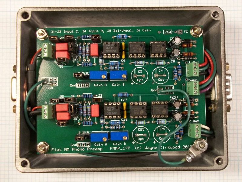
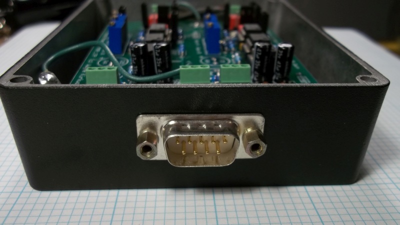
Phono Transfer System with remote flat phono preamp and RIAA EQ monitor switcher.
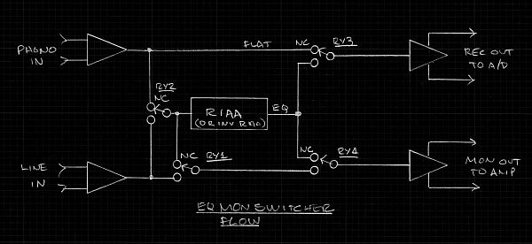
Flow diagram for Phono Transfer System with remote flat phono preamp and RIAA EQ monitor switcher.
Flat Balanced Input, Balanced Output Moving Magnet Phono Preamplifier
The preamp for the Phono Transfer System is designed to be remotely located at the turntable. Balanced outputs from the preamp feed the RIAA EQ/Monitor Switcher.
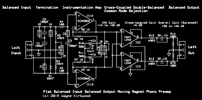
A Flat Balanced Input/Balanced Output Moving Magnet Phono Preamp
Phono Transfer System Flat Moving Magnet Preamp FMMP-18 Board Stuffing Guide.
Phono Transfer System Flat Moving Magnet Preamp FMMP-25 Board Stuffing Guide.
Preamp jumper options:
J1, J2, J3 input capacitance.
All open - No added load.
J1 is 50 pF. J1+J2 is 100 pF. J1+J3 is 150 pF. J1+J2+J3 is 200 pF.
J4 is input resistive load. Open is 99.8K, closed can be anything less than 99.8K.
With an added load of 88.7K in parallel (J4 closed) the input resistance is "47K" (46.96K).
J5 is the input configuration: Balanced or RCA coaxial.
When balanced, the input load to ground (common mode) is 49.9K/leg.
When J5 is jumpered unbalanced the "-" input is grounded and the input resistance is "100K" (99.8K). (J4 open. J4 closed 47K.)
There are two preamp gain trims for each channel.
J6 selects which gain adjustment pot is used.
This is for normal gain, typically 5 mV at 5 cm/s, and low gain for very hot, "+12 dB" dub plates.
Though it would likely not be quiet enough for MC inputs the jumper could also switch between MM and MC gains.
A MC head amp or transformer may also be used with the flat preamp.
Someone using the gain mode often would likely make the jumpers a switch or relay.
(I use them for setting either -10 or +4 dBu output gains.)
Flat Moving Magnet Preamp Circuit Description:
The fully-balanced input is an instrumentation amp having a gain of about +12 to +40 dB.
The preamp input is direct-coupled to the cartridge and DC-coupled up to the output.
Though op amp bias current flows in the cartridge when connected unbalanced most of the measured data I've seen shows no harmful effects.
Connected differentially however, only the offset current difference between op amps flows.
It is quite low being in the order of tens of nanoamps.
When the cartridge is connected to the input balanced, the output voltage offset is very low.
For moving magnet MM cartridges having the typical sensitivity of 5 mV at 5 cm/sec (1kHz) 18-20 dB of gain in this stage is plenty for RAW outputs.
AC Common mode rejection and an additional 6 dB of gain is realized in the Flat Preamp by a THAT1240 double-balanced line receiver.
The offset voltage from op amp input bias current - when a differential input cart connection is used - is primarily common mode and rejected by the THAT1240s.
For applications where connection lengths are short and balanced outputs are not wanted the second THAT1240 can be omitted.
When the companion RIAA EQ Monitor switcher board is used, the output coupling capacitors may be eliminated.
The RIAA EQ/Monitor switcher board has a downstream film interstage coupling cap to strip DC.
In free-standing applications, particularly those with high gain and unbalanced coaxial phono connections, output electrolytics may be used.
Preamp Noise Measurements:
I'm having difficulty making bandwidth-limited noise measurements and have no means to A-weight measurements.
Here is what I have so far:
The shielded twisted pair balanced DIN tonearm leads are about 3 feet.
The line output leads from the flat preamp are 48 feet feeding the RIAA EQ/Monitor protoboard.
I had NJM2068s already installed in the flat preamp so I used them.
It "sounds" quiet. Scary quiet.
I wanted to see what the noise level was when gain was set to produce +4dBu output.
The final output has 6 dB gain and the RIAA decoder was set to unity gain.
The remainder of the gain, all but 6 dB, was dialed into the preamp.
The ATR-96 MM cartridge is rated 5mv at 5 cm/s 1 kHz. They don't specify whether modulation is mono or single-channel.
The CBS STR-100 test record I'm using for level set is 3.54 cm/s with one channel modulated.
If I'm not mistaken this should work out to be 5 cm/s with both channels driven.
Based on that premise, I set the single channel gain to a reference level of +1 dBu.
Both channels driven should produce +4 dBu at 5 cm/s (lateral).
The RIAA EQ'd (but not A-weighted) output noise with a real cart (not a resistor), sitting on a real turntable, in a real room (with light dimmer EMI not a Faraday cage) produced an output noise floor of about -72 dBu.
This measurement bandwidth is 157 kHz. (fc=100 kHz.)
The signal to noise, unweighted, referenced to +4 dBu is about 76 dB.
A 20 kHz equivalent noise bandwidth and A-weighting will produce even better results.
AudioTester with a 22 kHz bandwidth is telling me SN should be around 78 to 79 dB.
Some of that is hum at Line and 2X, 3X and 5X line.
Its quiet, really quiet.
I suspect most of its quietness is from the balanced interface and common mode rejection.
Preamp Op Amp Choices:
The NJM2068 seems to be the quietest performer.
The NJM2114 and 5532 were about a dB noisier than the NJM2068.
For someone wanting a FET input, the OPA2134 worked pretty well.
It was about 3 dB noisier (with a resistive input termination) than the NJM2068.
The LME49720 and LME49860 were found to be unacceptable due to burst noise.
Maybe I have some bad ones. There is another user on the TI e2e forum with this same problem.
I later found that the OPA2134 is actually better with a cart, compared to a resistor, due to its lower current noise.
In the midrange the NJM2068, NJM2114 or NE5532 out-perform the OPA2134 where it's higher voltage noise dominates.
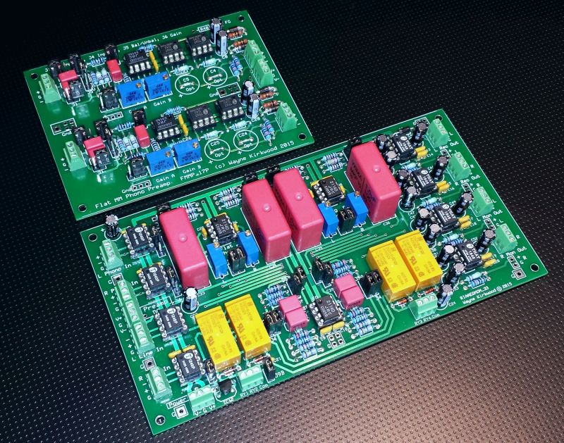
The Phono Transfer System RIAA EQ/Monitor Switcher
Flow diagram for Phono Transfer System with remote flat phono preamp and RIAA EQ monitor switcher.
The Phono Transfer System's EQ/Monitor Switcher is designed for direct connection to the DAW and Monitor Amplifer. The flat phono preamp output can be routed with or without RIAA de-emphasis to separate record and monitor outputs. Output from the DAW is connected to the Line In for playback monitoring. Playback monitoring can be routed to the Monitor Output with or without RIAA de-emphasis. The Line Input can also be routed to the record output with RIAA equalization applied. This permits analog EQ to be applied to flat recordings in situations where DSP-based de-emphasis is not desired.
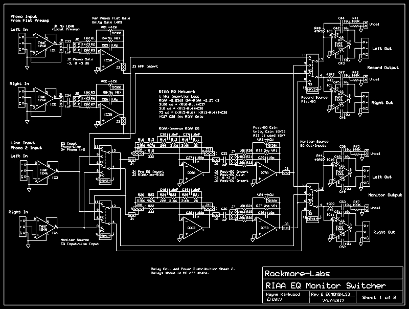
RIAA EQ, Inverse RIAA EQ and Monitor Switcher for the Flat Phono Preamp.
Note: The schematic above needs corrections to the relay designators and J9. It will be updated soon to match the PC board layout.
Phono Transfer System RIAA EQ Monitor Switcher Board Stuffing Guide.
RIAA EQ Monitor Switcher Signal Flow
The design has two signal paths. One is for recording the second for confidence monitoring or simultaneous recording and playback.
An RIAA EQ section can be placed in either the record path or playback path.
Flat transfers can be made through the record path while non-destructively switching monitor modes from monitoring flat record, record with EQ or playback from the DAW output.
Having analog RIAA EQ for monitoring saves ears and permits later de-clicking, done in the RAW un-EQ'd domain, to be heard in context.
Final EQ of the transfered files is done in DSP.
The flat balanced input/balanced output moving magnet preamp can be remotely located and powered from the monitor switcher permitting long cables between the turntable and workstation.
The flat/wideband preamp output is received by a THAT1240 line receiver.
It is then AC-coupled into a variable gain inverting buffer.
Relay RY3 selects either flat or RIAA EQ recording mode. RY2 must also be in Phono.
The operation of RY3 is destructive to recording.
The operation of RY2 is non-destructive to flat recordings.
The record out is available as an RCA connection or fully-balanced by a THAT1646.
The RIAA EQ section can be switched between the Record and Playback Monitor paths by RY2.
A post-EQ gain stage can be used to provide stepped gain trim and additional post-EQ gain if needed.
The DAW playback output is fed into the THAT1246-based line receiver.
RY3 selects either Flat or EQ'd monitoring from either the Play line input, Preamp Output or RIAA EQ output.
The operation of RY3 is non-destructive to recording.
RY1 switches the flat monitor source to either follow the RIAA EQ or the Line Input.
Jumper Description
J1 bypasses the balanced input stage. This is used when the flat preamp is in the same chassis as the EQ/Monitor Switcher.
When J1 is connected directly to the input, the THAT1240 on the EQ board and one THAT1240 on the flat preamp may be removed.
J2 (optional) permits the preamp gain to be raised or lowered in 3dB steps. It can also be a front panel switch.
J3 is a rumble/warp filter insert.
J4 is for alternate EQ. It can be used to bypass the RIAA stage and for inverse RIAA dub cutting allow the insert of a 50 kHz ultrasonic filter. (e.g. Neumann 2 pole SK)
J5A/J5B switch the RIAA filter to inverse RIAA to permit the board to be used for cutting discs.
J6 is an optional cartridge correction filter insert point. J6 may also be used to provide a return for alternate EQ.
J7 permits the post-EQ gain to be switched in 3 dB steps. J7 can also be used to sum cutterhead feedback with modulation.
J8 is a second playback cartridge correction filter insert. J8 can also be used for additional cutterhead EQ.
J9 selects relay power and ground from an on-board 12V regulator or external sources.
Board Stuffing Options
There are lots of them but these are the highlights.
The preamp gain can have an optional trim pot to adjust flat gain.
Gain is typically trimmed in the flat moving magnet preamp.
For moving coil preamps, fine adjustment of gain is not always possible.
A trim in this location allows minor amounts of "helper" preamp gain and adjustment of channel balance for moving coil carts.
If the flat preamp is located with the EQ/Monitor switcher the THAT1240 balanced input is not required.
The flat preamp can have one THAT1240 removed.
Due to signal inversion, the inverting output of the flat preamp and inverting input of the EQ board are used to maintain correct polarity.
This is also the reason the THAT1240 appears "upside down" with the + input connected to the - THAT1240 input.
For applications which do not require post-EQ gain trim it may be eliminated.
More construction information will be posted here as it becomes available.
Related Articles
RIAA and Inverse RIAA vst and Nyquist Plugins and Tools https://www.lathetrolls.com/viewtopic.php?f=1&t=7219
Reference Level and Cartridge Transfer Factor https://www.lathetrolls.com/viewtopic.php?f=1&t=7174
Vinyl Polarity Relationships in the Westrex 45/45 System https://www.lathetrolls.com/viewtopic.php?f=1&t=6661
A Super-Simple Budget Fully-Balanced Tonearm Cable https://www.lathetrolls.com/viewtopic.php?f=9&t=5876
A Flat Moving Magnet Balanced In/Out Preamp for RAW Transfer https://www.lathetrolls.com/viewtopic.php?f=9&t=5914
A Dual Path RIAA EQ/Monitor Switcher for RAW Transfers https://www.lathetrolls.com/viewtopic.php?f=9&t=5915
RIAA/Inverse RIAA Circuit - Jumper Selectable https://www.lathetrolls.com/viewtopic.php?f=9&t=5848
Balanced Tonearm Wiring. FFT comparison between balanced and unbalanced phono wiring. https://www.vinylengine.com/turntable_f ... 88#p818402