
MTC-MS-II PC Boards: https://ka-electronics.com/shop/index.p ... ch=ms%20II
Updated October 10, 2023: MTC-MS-II Assembly Instructions: https://www.ka-electronics.com/images/p ... 2323_1.pdf
Updated October 20, 2022: Tilt and Width Stepped Switch Wiring: viewtopic.php?t=1270
Updated June 20, 2021: BOM for MSII V37 Boards: https://www.mouser.com/ProjectManager/P ... 59fbdeac53
Remember that if you ordered THAT ICs as part of your PC board "kit" be sure to remove them from your shopping cart at Mouser before ordering.
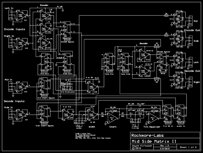
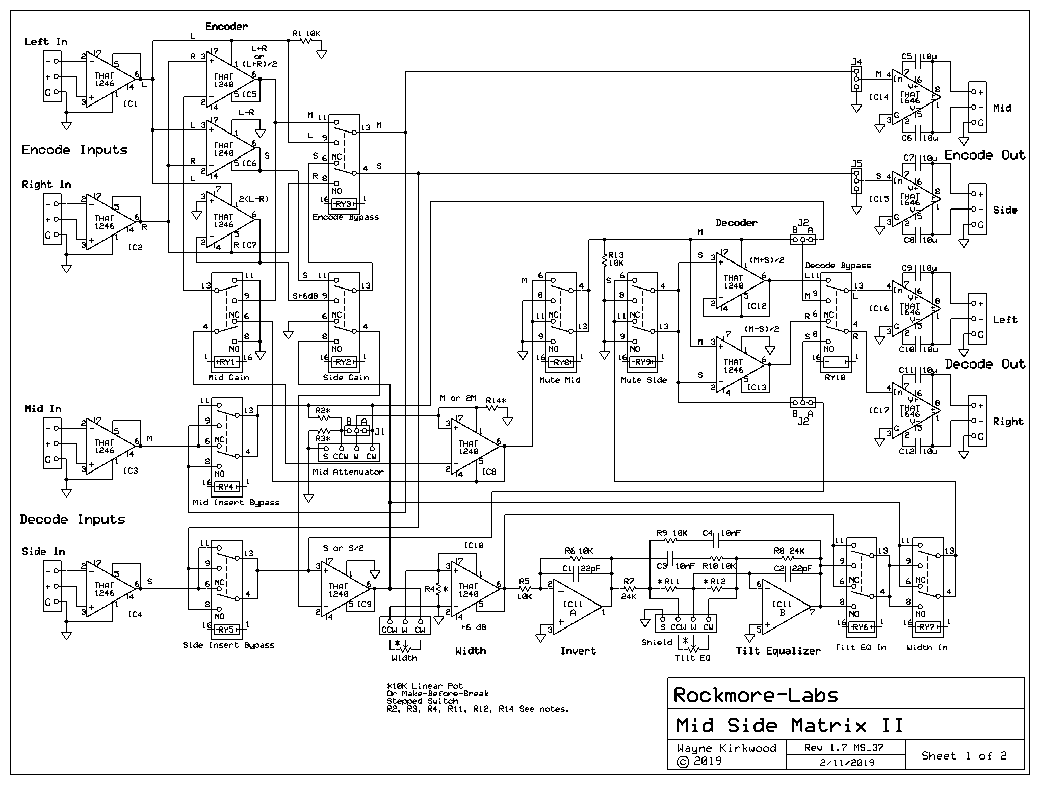
The KA-Electronics MTC-MS-II Improved Precision Mid Side Matrix for Audio Mastering
Large format schematic for the MTC-MS-II: https://www.ka-electronics.com/images/p ... heet_1.png
The MTC-MS-II board includes a number of new features to make MS work easier.
MTC-MS-II Unique Insert Gain Offset:
Side levels are often significantly lower than Mid. With highly-correlated elements Mid often has "mono build-up" producing level increases of 3 to 6 dB.
The MTC-MS-II addresses MS level challenges by applying Insert Gain Offset between Mid and Side. The Encoder can operate with 0, 6 and 12 dB offset between Mid and Side. When gain offset is applied in the Encoder, the Decode gain is compensated to maintain the original M/S ratio.
Mid Gain Offset: Reduces Mid Encode Gain by -6 dB. Mid Decode Gain is automatically increased by +6 dB to compensate. Headroom is increased by 6 dB.
Side Gain Offset: Increases Side Encode Gain by +6 dB. Side Decode Gain is decreased by -6 dB. Side gain offset allows outboard gear to be driven hotter.
By using Mid and Side Gain offset together, an offset up to 12 dB is available.
Individual Encode Decode Bypass
The MTC-MS-II's Encoder can be bypassed to forward Left and Right into the Insert.
The Decoder can be also be bypassed to forward Mid/Side to the final Left and Right Outputs (J2B) or jumper-configured to forward the Decode inputs directly to the output. (J2A)
By using Encode and Decode bypass together the Insert can be switched from Mid/Side to Left/Right.
Individual Insert Bypass
Mid and Side have individual Insert bypass relays. Need to compress only Mid? Bypass the Side Insert completely.
Processing both Mid and Side? Bypass one at a time to hear each processes' contribution.
On-board relay logic is available to bypass Mid and Side Inserts simultaneously for instant A/B comparisons.
On-board Width Control
The MTC-MS-II has on-board Width control ranging from 0 to 200% by varying Side Level from -∞ to +6 dB relative to an anchored unity gain Mid level.
Control is smooth and predictable with a "feel" similar to the Width Controller using the LR±S method. A potentiometer or stepped make-before-break rotary switch can be used. The Width Control is relay-bypassed.
On-board Tilt Equalizer Provides Frequency-Dependent Width
A gentle tilt equalizer can be inserted into the Side channel to provide frequency-dependent Width. The range at 10 kHz is +/-3dB. As 10 kHz is boosted, 100 Hz is decreased by an identical amount with a "pivot" frequency of 1 kHz. A 0 to 6 dB range in frequency-dependent Width is available from the 100 Hz to 10 kHz with either positive or negative slope. Width can increase with frequency or decrease with frequency.
The Tilt Equalizer follows the overall Width control and is relay-bypassed.
Individual Mid and Side Pre-Decode Mutes
The Mid and Side channels have individual relay mutes to audition the processing of each insert.
When Mid is muted, Side is presented to the Left and Right outputs in their actual perspective similar to an "in place" Solo function.
(Side is a "mono" single-channel signal. When presented "in place" the positive polarity is heard in Left and the negative in Right. This is how we hear it in the stereo image when recombined with Mid.)
The Mid and Side channel mutes are placed in the return path rather than the Insert Send to eliminate "compressor recovery" artifacts from muting sends.
Improved Encoder and Decoder Headroom
Mid Side encoding is well-known for Mid "build-up" on highly-correlated material.
The MTC-MS-II eliminates Mid build-up and the resulting headroom reduction with Mid Gain offset. Internal headroom in the Mid channel is increased by 6 dB to +23 dBu. The external overload point is +27 dBu. (+/-15V supply rails.)
Though not fully-appreciated Mid Side decoding has additional gain build-up during Left and Right reconstruction. When M+S is added to M-S to produce "L" the actual result is 2L.
The MTC-MS-II uses a combination of THAT1240 and THAT1246 line receivers to eliminate encoding and decoding headroom and level bottlenecks. By switching the THAT1240 in a unique way its gain can be varied from -6, to 0 and to +6 dB. This eliminates the requirement for additional gain or attenuation stages that would add a differential phase delay to one process path but not the other. High frequency crosstalk performance is maintained.
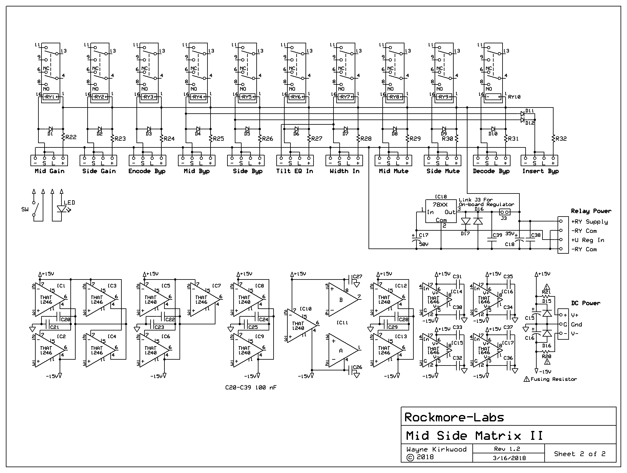
Relay and Power Distribution
Note: Updated drawing to MS_36 layout to link Tilt Relay and LED to Width Relay.
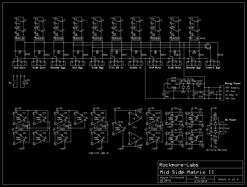
Large format schematic for the MTC-MS-II Relay and Power Distribution: https://www.ka-electronics.com/images/p ... et_2_1.png
