incredible. I will have my phone off all July, but will check in weekly on laptop - very cool stuff Wayne, I will read through the last posts you made sine 6.27 when I have time. thanks for doing all this - I am very happy how the last 6+ months have turned out since first speaking with you.
-jeffrey
The Waveulator: Two VCA-based Clipper Saturators
-
TheeAldeen
- Posts: 15
- Joined: Wed Dec 28, 2022 11:10 pm
-
mediatechnology

- Posts: 5473
- Joined: Sat Aug 11, 2007 2:34 pm
- Location: Oak Cliff, Texas
- Contact:
Re: The Waveulator: Two VCA-based Clipper Saturators
Thanks Jeffrey!
I updated the schematic to provide component designators and will be posting a circuit description below it later.
Waveulator ME Mastering Edition Schematic 081723
I updated the schematic to provide component designators and will be posting a circuit description below it later.
Waveulator ME Mastering Edition Schematic 081723
Re: The Waveulator: Two VCA-based Clipper Saturators
Looking amazing Wayne!
Comparing this to your previous schematics it seems like it wouldn't be a terribly difficult mod to add expansion back in by allowing the detector to drive either the + or - side of IC12B (and IC13B), correct? I understand it doesn't really make sense on a mastering clipper, but if it's simple to put it on a switch I'd certainly use it for processing percussive tracks.
Comparing this to your previous schematics it seems like it wouldn't be a terribly difficult mod to add expansion back in by allowing the detector to drive either the + or - side of IC12B (and IC13B), correct? I understand it doesn't really make sense on a mastering clipper, but if it's simple to put it on a switch I'd certainly use it for processing percussive tracks.
-
mediatechnology
- Posts: 5473
- Joined: Sat Aug 11, 2007 2:34 pm
- Location: Oak Cliff, Texas
- Contact:
Re: The Waveulator: Two VCA-based Clipper Saturators
Thank you!gzifcak wrote: ↑Sun Jul 09, 2023 1:56 pm Looking amazing Wayne!
Comparing this to your previous schematics it seems like it wouldn't be a terribly difficult mod to add expansion back in by allowing the detector to drive either the + or - side of IC12B (and IC13B), correct? I understand it doesn't really make sense on a mastering clipper, but if it's simple to put it on a switch I'd certainly use it for processing percussive tracks.
What I did a couple of weeks ago to experiment with Expansion was by modifying the non-inverting inputs of IC15 and IC16.
Add a 249Ω to ground and a resistor >>10KΩ to a switch and then switch the outputs of IC12 and IC13B to the non inverting inputs.
I say >>10KΩ because a little goes a very long way when the control response is linear/expo.
It's quite unfriendly to tweeters and midrange drivers when it pops supper-hard.
I discovered that the differential Ec driver could be made into a "Birt Driver" by feeding the outputs of IC15B and IC16B into the non-inverting inputs of the "A" op amps through a 10KΩ. A Birt Driver makes the noise contribution of IC15B/IC16B invisible to the 2180 since Ec+ and Ec- provide common mode rejection of the noise component. It may not matter however as the exponential response of Ec thresholds out lower-level noise.
Re: The Waveulator: Two VCA-based Clipper Saturators
Awesome, thank you for the explanation.
-
mediatechnology
- Posts: 5473
- Joined: Sat Aug 11, 2007 2:34 pm
- Location: Oak Cliff, Texas
- Contact:
Waveulator ME Circuit Description
Edited 8/17/23 to update the schematic and circuit description.
Waveulator ME Mastering Edition Schematic 81023
Waveulator ME Circuit Description
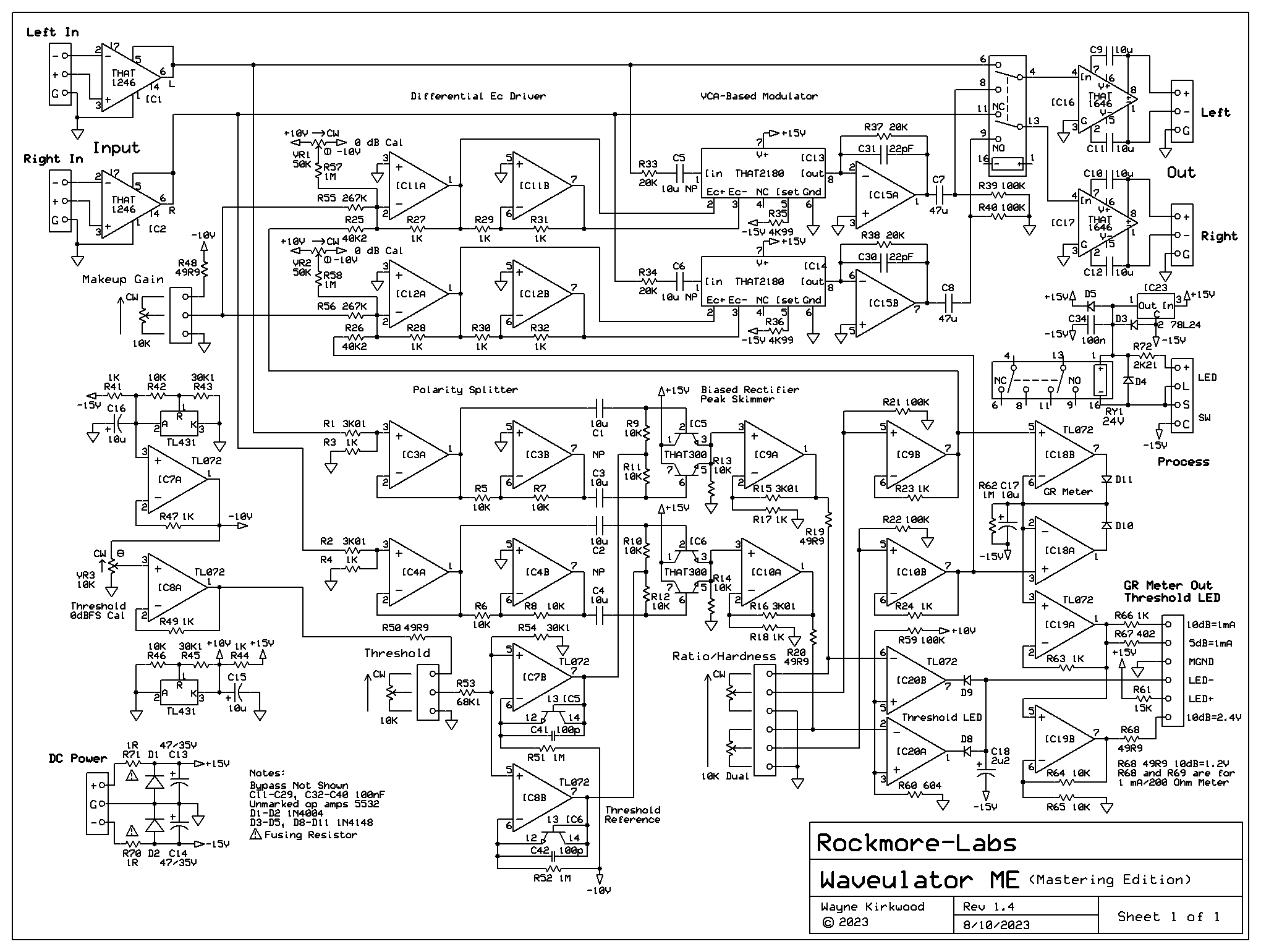
The Waveulator has two signal paths per channel: Audio and Modulator Sidechain. Its' topology is almost identical to a conventional feed-forward compressor/limiter with the primary difference being the absence of any signal averaging. The Waveulator is a zero-attack zero-release limiter that does not operate on signal history.
Audio Path
The Waveulator ME's audio path is simple. The balanced input is received by a THAT1246 providing 6 dB of attenuation. Using +/-15V supplies and, for a nominal 0 dBu input, the internal headroom is 27 dB with an overload point at the output of IC1/IC2 of approximately +/-13V peak.
The outputs of the line receivers route to the VCA inputs and the bypass relay.
The VCAs are THAT2180 wih IC15A and IC15B providing current-to-voltage "IV" conversion. The outputs of IC15 route to the bypass relay's normally open "NO" connections.
Relay RY1 provides a soft bypass function.
THAT1646 OutSmarts® rebalance the signal path and provide 6 dB of gain. The overall gain is unity.
Modulator Sidechain
The Waveulator, which is a combination of the words "Wave" and "Modulator," operates by modulating the signal with a rectified version of itself. A VCA is used as the multiplier to provide modulation. The audio input to the VCA is the carrier, the control voltage, "Ec," is the modulation input.
When a full-wave absolute value rectified copy of the carrier waveform is used as a modulation source, the even-order modulation causes odd-order symmetrical products to be produced at the modulator output. In the Waveulator, these symmetrical products are used to provide peak limiting.
A more familiar analogy is an above threshold feed-forward peak limiter. Rather than operate on the signal average, the Waveulator operates directly on the waveform. A conventional Threshold control sets the breakpoint on the waveform where limiting begins. A Ratio control sets the slope or "hardness" of the waveform limiting and a "Make-up" gain control restores level compressed by "Waveulation."
The left channel of the sidechain is described. The right channel is separate and identical. The only common controls shared by the two channels are DC levels for Threshold and Make-up Gain and a dual gang pot (or two pole stepped switch) for Ratio which controls gain.
The Waveulator sidechain is actually quite simple. Two-thirds of the op amps are simply buffers or voltage references. The heart of the sidechain is an absolute value rectifier formed by IC3A, IC3B and IC5 a THAT300 transistor array.
Transistor-based rectifiers offer a number of advantages but one significant disadvantage is that the reverse breakdown voltage is quite low, typically -6 to -8V for NPN devices. To prevent reverse breakdown the input voltage to the detector stage is attenuated by 12dB which is a factor of 4. The THAT1246 input's maximum output, typically -13V with +/-15V supplies, limits the maximum attenuated peak value to -3.25V. R1 and R3 provide the required attenuation.
IC3A buffers the attenuator and its' output feeds the base of THAT300 transistor Q1 (pin 2) through a bipolar coupling capacitor. IC3B inverts the output of IC3A and feeds the base of Q2 (pin 6) through a bipolar coupling capacitor to polarity invert negative peaks prior to rectification.
Q1 and Q2 are pre-biased by resistors R9, R11, IC7B, THAT300 Q4 (pins 12-14) and R51. When the wiper of the Threshold pot is at 0V Q1 and Q2 are pre-biased by approximately 12 uA set by R51. When the wiper is at 0V the detector operates with full dynamic range.
Q1 and Q2 full-wave rectify the attenuated input and provide a ground-referred absolute value across R13. IC9A buffers the absolute value rectifier and provides gain to restore the input attenuation.
The Waveulator's absolute value circuit, inspired by Cordell, operates open loop. There are no active devices in the feedback loop of an op amp to create small "hooks," "kinks" and steps in the rectified waveform.
The Waveulator requires a Threshold control to raise the rotation point so it operates only on waveform peaks. An adjustable negative offset introduced into the noninverting input of IC7B keeps IC5's Q1 and Q2 into cutoff until the crest of the waveform is reached. When the absolute value of the input exceeds the Threshold level Q1 and Q2 begin to conduct and rectify. This results in the peaks or crests of the wavefrom being "skimmed off" with the skimmed off portion of the waveform becoming ground-referred at the emitters. This becomes the modulating waveform.
The actual upper limit for Threshold can be calibrated to the converter's 0 dBFS full scale reference by adjusting VR3. IC8A buffers the adjustable 0 dBFS reference. IC7A provides a buffered -10V reference voltage for the sidechain.
The THAT300 datasheet does not specify a maximum safe reverse emitter-base breakdown voltage. A quick check with THAT confirms that the devices are screened with a typical value of -7.93V and any part measuring less than -6V is rejected. The maximum negative-going peak value of the input waveform is -3.25V. A threshold equal to -3.25V (or slightly greater) is required to prevent detection with +27 dBu inputs. The sum of the negative peak input, the threshold and pre-bias Vbe need to be held to a value less than -8V with -6V being a goal. -3.25V + -3.25V + 0.5V is -6V. The actual Vbe may be slightly higher so a value near -6V is achieved.
The modulating waveform at the output of IC9A feeds the Ratio/Hardness control which defines the slope of limiting above the rotation point set by the Threshold control. IC9B buffers the wiper of the Ratio control before feeding it to the modulator driver. The output of IC9B also feeds gain reduction metering. The scale factor is approximately +120 mV per dB.
IC11A and IC11B provide an attenuated differential drive to modulate the THAT2180's Ec+ and Ec- control ports. The control scale factor of a THAT2180 is approximately 6 mV per dB. IC15A attenuates the +120 mV/dB input scaling to -3 mv/dB owing to its attenuation factor of 40. IC11B inverts IC11A's output. The net attenuation factor is 20.
Differential modulation was chosen to reduce the possibility of modulation signal feedthrough to the final output.
A Makeup gain control injects an offset into IC11A to allow level normalization after peak limiting. VR1 trims the processed gain to unity when modulation is absent.
The detector/peak skimmer operates in the linear domain. The THAT2180's modulation ports have an exponential response. When the two "laws" are used together the modulation is less harsh and the perceived distortion is less. When modulation begins to establish a breakpoint in the waveform it first does so gently with an ever-increasing rate similar to "Over Easy" compression.
Waveulator ME Mastering Edition Schematic 81023
Waveulator ME Circuit Description
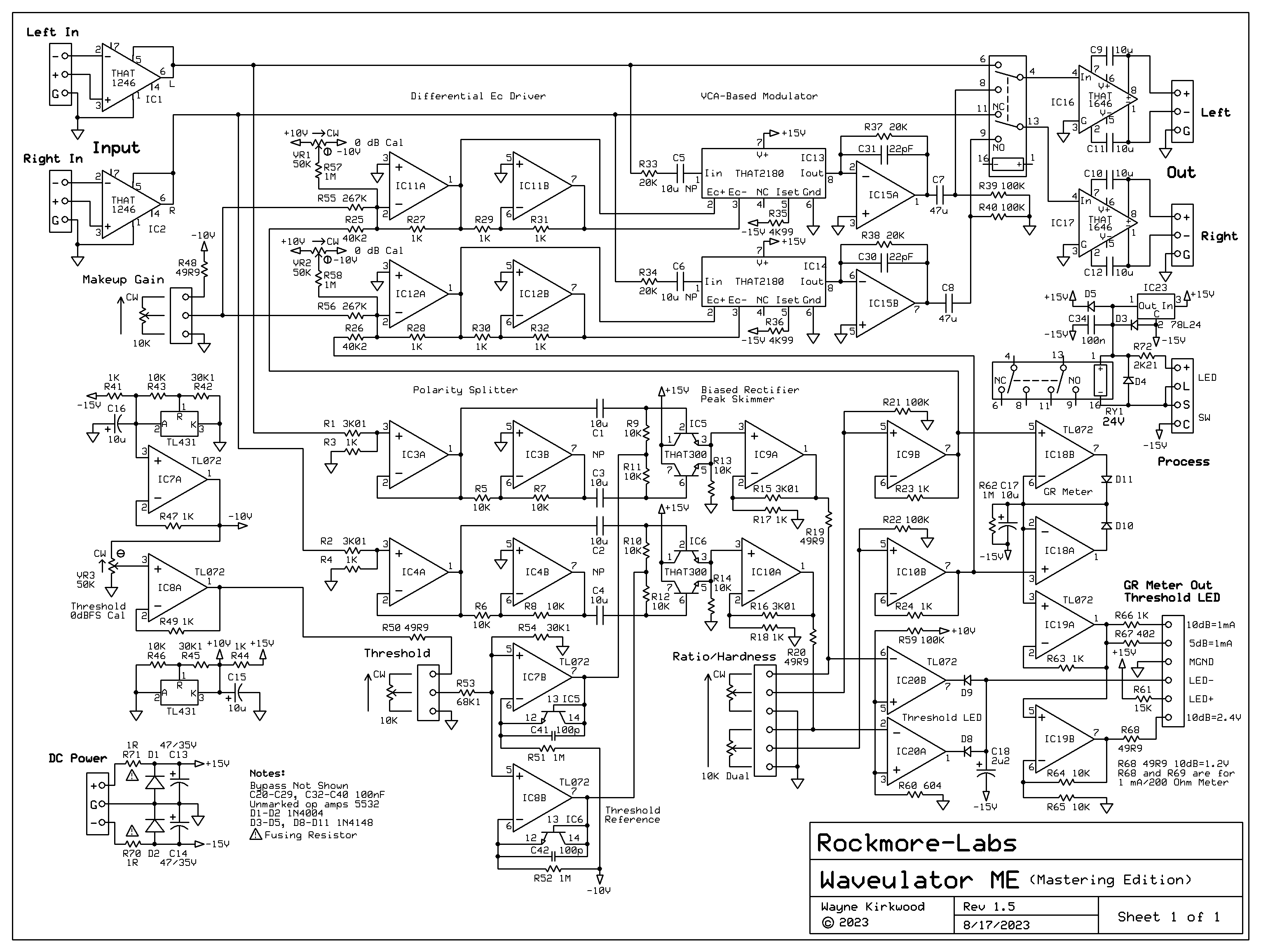
The Waveulator has two signal paths per channel: Audio and Modulator Sidechain. Its' topology is almost identical to a conventional feed-forward compressor/limiter with the primary difference being the absence of any signal averaging. The Waveulator is a zero-attack zero-release limiter that does not operate on signal history.
Audio Path
The Waveulator ME's audio path is simple. The balanced input is received by a THAT1246 providing 6 dB of attenuation. Using +/-15V supplies and, for a nominal 0 dBu input, the internal headroom is 27 dB with an overload point at the output of IC1/IC2 of approximately +/-13V peak.
The outputs of the line receivers route to the VCA inputs and the bypass relay.
The VCAs are THAT2180 wih IC15A and IC15B providing current-to-voltage "IV" conversion. The outputs of IC15 route to the bypass relay's normally open "NO" connections.
Relay RY1 provides a soft bypass function.
THAT1646 OutSmarts® rebalance the signal path and provide 6 dB of gain. The overall gain is unity.
Modulator Sidechain
The Waveulator, which is a combination of the words "Wave" and "Modulator," operates by modulating the signal with a rectified version of itself. A VCA is used as the multiplier to provide modulation. The audio input to the VCA is the carrier, the control voltage, "Ec," is the modulation input.
When a full-wave absolute value rectified copy of the carrier waveform is used as a modulation source, the even-order modulation causes odd-order symmetrical products to be produced at the modulator output. In the Waveulator, these symmetrical products are used to provide peak limiting.
A more familiar analogy is an above threshold feed-forward peak limiter. Rather than operate on the signal average, the Waveulator operates directly on the waveform. A conventional Threshold control sets the breakpoint on the waveform where limiting begins. A Ratio control sets the slope or "hardness" of the waveform limiting and a "Make-up" gain control restores level compressed by "Waveulation."
The left channel of the sidechain is described. The right channel is separate and identical. The only common controls shared by the two channels are DC levels for Threshold and Make-up Gain and a dual gang pot (or two pole stepped switch) for Ratio which controls gain.
The Waveulator sidechain is actually quite simple. Two-thirds of the op amps are simply buffers or voltage references. The heart of the sidechain is an absolute value rectifier formed by IC3A, IC3B and IC5 a THAT300 transistor array.
Transistor-based rectifiers offer a number of advantages but one significant disadvantage is that the reverse breakdown voltage is quite low, typically -6 to -8V for NPN devices. To prevent reverse breakdown the input voltage to the detector stage is attenuated by 12dB which is a factor of 4. The THAT1246 input's maximum output, typically -13V with +/-15V supplies, limits the maximum attenuated peak value to -3.25V. R1 and R3 provide the required attenuation.
IC3A buffers the attenuator and its' output feeds the base of THAT300 transistor Q1 (pin 2) through a bipolar coupling capacitor. IC3B inverts the output of IC3A and feeds the base of Q2 (pin 6) through a bipolar coupling capacitor to polarity invert negative peaks prior to rectification.
Q1 and Q2 are pre-biased by resistors R9, R11, IC7B, THAT300 Q4 (pins 12-14) and R51. When the wiper of the Threshold pot is at 0V Q1 and Q2 are pre-biased by approximately 12 uA set by R51. When the wiper is at 0V the detector operates with full dynamic range.
Q1 and Q2 full-wave rectify the attenuated input and provide a ground-referred absolute value across R13. IC9A buffers the absolute value rectifier and provides gain to restore the input attenuation.
The Waveulator's absolute value circuit, inspired by Cordell, operates open loop. There are no active devices in the feedback loop of an op amp to create small "hooks," "kinks" and steps in the rectified waveform.
The Waveulator requires a Threshold control to raise the rotation point so it operates only on waveform peaks. An adjustable negative offset introduced into the noninverting input of IC7B keeps IC5's Q1 and Q2 into cutoff until the crest of the waveform is reached. When the absolute value of the input exceeds the Threshold level Q1 and Q2 begin to conduct and rectify. This results in the peaks or crests of the wavefrom being "skimmed off" with the skimmed off portion of the waveform becoming ground-referred at the emitters. This becomes the modulating waveform.
The actual upper limit for Threshold can be calibrated to the converter's 0 dBFS full scale reference by adjusting VR3. IC8A buffers the adjustable 0 dBFS reference. IC7A provides a buffered -10V reference voltage for the sidechain.
The THAT300 datasheet does not specify a maximum safe reverse emitter-base breakdown voltage. A quick check with THAT confirms that the devices are screened with a typical value of -7.93V and any part measuring less than -6V is rejected. The maximum negative-going peak value of the input waveform is -3.25V. A threshold equal to -3.25V (or slightly greater) is required to prevent detection with +27 dBu inputs. The sum of the negative peak input, the threshold and pre-bias Vbe need to be held to a value less than -8V with -6V being a goal. -3.25V + -3.25V + 0.5V is -6V. The actual Vbe may be slightly higher so a value near -6V is achieved.
The modulating waveform at the output of IC9A feeds the Ratio/Hardness control which defines the slope of limiting above the rotation point set by the Threshold control. IC9B buffers the wiper of the Ratio control before feeding it to the modulator driver. The output of IC9B also feeds gain reduction metering. The scale factor is approximately +120 mV per dB.
IC11A and IC11B provide an attenuated differential drive to modulate the THAT2180's Ec+ and Ec- control ports. The control scale factor of a THAT2180 is approximately 6 mV per dB. IC15A attenuates the +120 mV/dB input scaling to -3 mv/dB owing to its attenuation factor of 40. IC11B inverts IC11A's output. The net attenuation factor is 20.
Differential modulation was chosen to reduce the possibility of modulation signal feedthrough to the final output.
A Makeup gain control injects an offset into IC11A to allow level normalization after peak limiting. VR1 trims the processed gain to unity when modulation is absent.
The detector/peak skimmer operates in the linear domain. The THAT2180's modulation ports have an exponential response. When the two "laws" are used together the modulation is less harsh and the perceived distortion is less. When modulation begins to establish a breakpoint in the waveform it first does so gently with an ever-increasing rate similar to "Over Easy" compression.
-
TheeAldeen
- Posts: 15
- Joined: Wed Dec 28, 2022 11:10 pm
Re: The Waveulator: Two VCA-based Clipper Saturators
i'm almost caught up - I am beyond impressed & very grateful you chose to make this a full-blown module/board from your past project with your friend. if I would have made your original post on PCB & never checked back to this forum board - I would have really missed out.mediatechnology wrote: ↑Sun Jul 09, 2023 11:05 am Thanks Jeffrey!
I updated the schematic to provide component designators and will be posting a circuit description below it later.
Waveulator ME Mastering Edition Schematic
viewing your hand drawn diagrams will never get old - looking forward to this build, as well as future modules, ideas & forum posts like this - what a great way to finish off the year.
-
mediatechnology
- Posts: 5473
- Joined: Sat Aug 11, 2007 2:34 pm
- Location: Oak Cliff, Texas
- Contact:
Re: The Waveulator: Two VCA-based Clipper Saturators
I've been having to spend some "quality time" with the mower and string trimmer doing deferred lawn maintenance around the Pink Atomic Ranch. With temps hovering around 100°F in North Texas - which is typical - work gets done from around 8AM-12:30PM. I haven't had much time or energy to spend on the workbench.
I did manage to get the Threshold LED winky built up and have given considerable thought to GR metering as I bake in the sun.
I think that due to real estate on the main board I may opt for a 120 mV/dB voltage and 1 mA analog meter output with bar graph metering off-board.
I'm torn between an LM3914 design or one made with quad LM324 op amps.
TI discontinued the DIP LM3914 eons ago but it looks like Chinese manufacturers have either reverse-engineered it, or bought masks or die from TI.
The HLF LM3914 datasheet is a copy of the National one: http://www.hlf-ic.cn/en/products/show-40.html
Unfortunately I can't find the HLF LM3914 in stock.
A quick search of eBay or Amazon shows no shortage of LM3914s or simple meters based on them including parts made by Todys. (sp?)
Using the LM3914 I could resurrect the Pico Compressor's GR-10 and GR-20 10 and 20 step meters.
A quad comparator-based design, which I have, would be a larger board than the GR-10 and GR-20.
In the meantime I'm going to build the 1 mA output and see how it looks on a mechanical meter.
-
TheeAldeen
- Posts: 15
- Joined: Wed Dec 28, 2022 11:10 pm
Re: The Waveulator: Two VCA-based Clipper Saturators
its hilarious the level of detail your posts have that I cannot follow - but can completely appreciate the level of passion & dedication - this has been truly a pleasure login in & following up on this forum weekly to read these.
sounds like the yard work has been nice - my current place has a landscaper do all the neighborhood lawns - its very "different" having another man mow your lawn - specially when I am more than capable (and enjoy the work myself). but he has been cutting the grass here long before I moved in - and - I was told he even planted it himself - so I guess its his baby and not my own.
anyways, aside from the yard work, that heat is a bit much, my brain melts at anything over 77-80 *F. I would never be able to survive that Big-Tex environment.
for the music and electronics - I had a milestone which made me pull up this forum and comment
//
the internet course I was going through used SUBMISSIONAUDIO flatline (clipper) & Fab's L2 (limiter) - and it was weird, I have not really done any tutorials or online classes in a long time - and it was crazy realizing how most of my audio gear is now physical, when it used to for so long be software plugins,
I am not a professional mixologist, or mastering engineer or engineer of electronics - just enjoy music really - so it has been crazy trying to find my "place" in this large school of professionals
I guess the yard work I related to - I am a bit envious I will say
//
and how everything was so digital for so long -
its nice to see it all break away for myself & become more physical and finite
and how this Waveulator build is physical - and well, completely custom & handmade...
and how I can literally check-in and read up on the thing as it is being conceived, designed, demo'd ...its truly crazy
its like waking up and realizing I am on the other side of the "wall" and its just a very humbling and gratifying feeling to be a part of
//
its just one of those milestones I guess
thanks Wayne - will check your forum and everyones posts again in a week,
always a pleasure seeing new posts and what has been happening
BTW, I saw spinal tap for the first time - and the "goes to 11" jokes finally make sense ;]
-
mediatechnology
- Posts: 5473
- Joined: Sat Aug 11, 2007 2:34 pm
- Location: Oak Cliff, Texas
- Contact:
Re: The Waveulator: Two VCA-based Clipper Saturators
So I finally got some time in the house alone and can work. For the last week or so it's been tough. You normally think of cabin fever being something that happens in the wintertime but, here in Texas, with normal daily highs being around 100° you can get cabin fever in the summer and winter.
I had previously worked into the Protoboard the above threshold winky and today got a simple analog gain reduction meter output running.
It's nice not to be flying blind and actually see GR. It's hard to read on a scope looking at the modulation waveform.
I need to find a good use for a second half of an unused dual op amp. I think I'll provide an expanded scale output.
Currently 1 mA FS is 10 dB GR. A 5 dB FS selection seems like a good thing to have.
While I ponder the unused op amp I think I'll update the docs and start the layout...