The Waveulator: Two VCA-based Clipper Saturators
Re: The Waveulator: Two VCA-based Clipper Saturators
agree on 5dB
Best,
Doug Williams
Electromagnetic Radiation Recorders
Doug Williams
Electromagnetic Radiation Recorders
-
mediatechnology

- Posts: 5473
- Joined: Sat Aug 11, 2007 2:34 pm
- Location: Oak Cliff, Texas
- Contact:
Re: The Waveulator: Two VCA-based Clipper Saturators
I updated the schematic to include the threshold winky LED and Gain Reduction meter outputs.
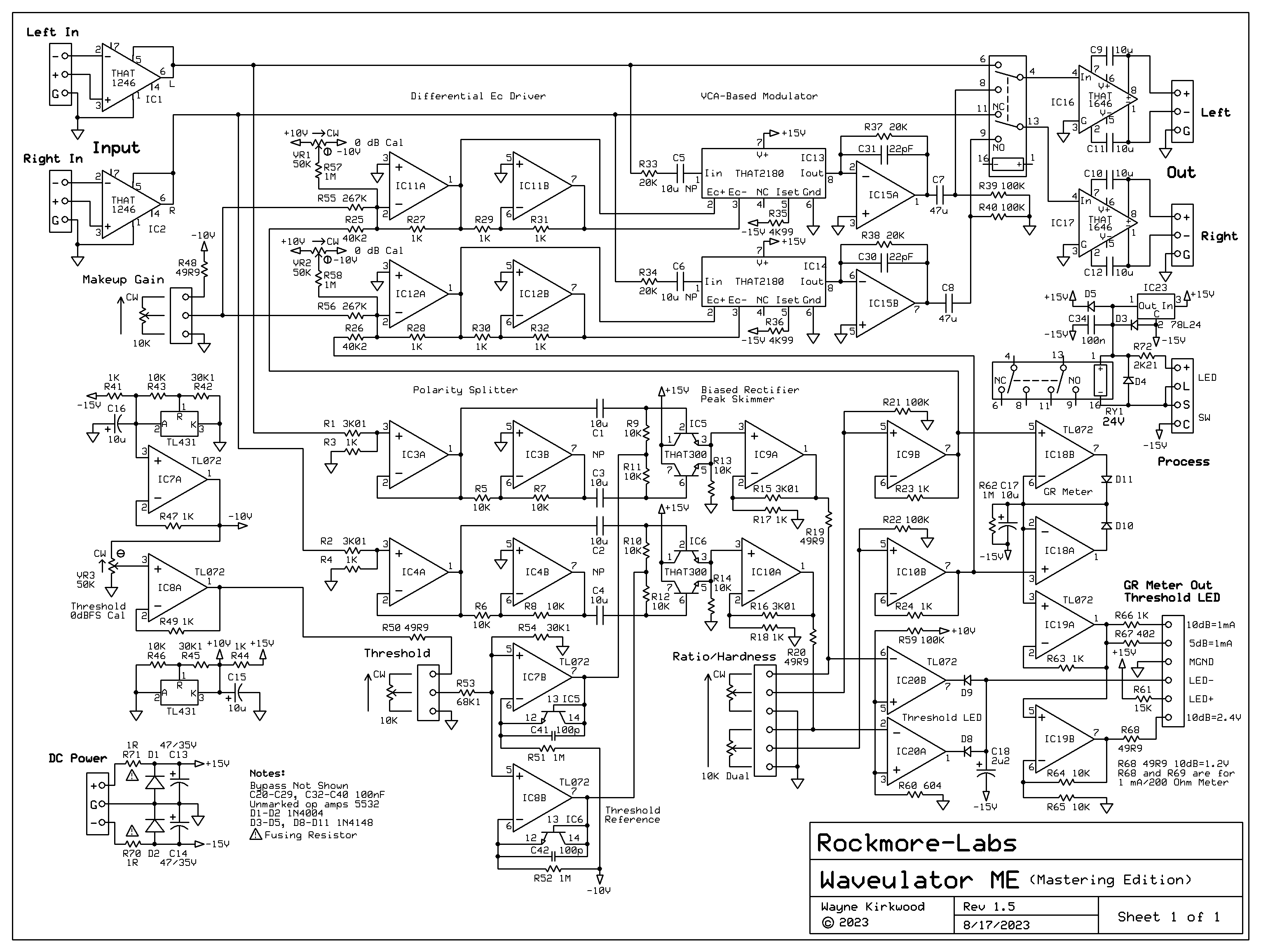
Waveulator ME Mastering Edition Schematic 081723
IC20 lights an LED when the threshold is exceeded by about 1/2 dB.
IC18 is a peak detector which samples the higher of the two channels.
IC19 buffers the GR peak detector and provides both current and voltage outputs. The values of R66 and R67 depend on the internal resistance of the 1 mA meter. 10 dB GR is about 1.2V. The total resistance should be 1.2K so the actual build-out is 1200Ω-Rmeter for 10 dB FS and 600Ω-Rmeter for 5 dB FS. When a voltage bargraph meter is used R69 should be 49R9. IC19B provides a gain of 2 for a scale factor of 240 mV/dB.
-
mediatechnology
- Posts: 5473
- Joined: Sat Aug 11, 2007 2:34 pm
- Location: Oak Cliff, Texas
- Contact:
Re: The Waveulator: Two VCA-based Clipper Saturators
The two unused transistors in the pair of THAT 300s are burning a hole in my pocket and I think I just figured out a use for them.gzifcak wrote: ↑Sun Jul 09, 2023 1:56 pm Looking amazing Wayne!
Comparing this to your previous schematics it seems like it wouldn't be a terribly difficult mod to add expansion back in by allowing the detector to drive either the + or - side of IC12B (and IC13B), correct? I understand it doesn't really make sense on a mastering clipper, but if it's simple to put it on a switch I'd certainly use it for processing percussive tracks.
The best expansion effect I got was the overall linear system where the detector was log and the VCA control response exponential.
I'm thinking I may use the left-over transistor or diode-connected transistor as a log amp for an optional expansion mode.
I may not be able to work it into this layout but for a device that would have both compression and expansion modes it might just work.
I need to add power distribution to the schematic and then start the layout. What I might do on this layout is provide an insert jumper at the output of IC12A and IC13A that could be used to insert an inverting log amp. By virtue of it being inverting the control response switches from compression to expansion along with switching from expo to linear overall.
-
mediatechnology
- Posts: 5473
- Joined: Sat Aug 11, 2007 2:34 pm
- Location: Oak Cliff, Texas
- Contact:
Re: The Waveulator: Two VCA-based Clipper Saturators
To attempt upward expansion I added a diode clamping circuit which produces, in the detector output, a linear response then log at one diode drop. When combined with the expo response of the VCA the overall response is exponential then linear. Having this stage prevents huge amounts of upward expansion. It's not the same as what we heard previously which was full log-expo.
The clamping stage was inverting and placed prior to the ratio/hardness control so I didn't have to invert Ec.
This temporarily disabled my metering but I got a chance to listen to it and liked what I heard and wanted a little more range.
It provides an impact-restoration effect.
Finding the threshold sweet spot is a little more difficult because it needs to be low enough to just bite into the middle of the waveform so the RMS level is just bumping up against the threshold.
Expanding the high-level peaks alone doesn't give a pronounced effect - it's got to have some "bite" into the average level to do its thing.
For now I'll try to work in jumpers for an experimental insert.
More work needs to be done to implement expansion.
For now, in order to move forward, I think I'll start on a layout for compression only.
Re: The Waveulator: Two VCA-based Clipper Saturators
Nice! Excited to hear this version of the expansion at some point.
Re: The Waveulator: Two VCA-based Clipper Saturators
Coming together….
Best,
Doug Williams
Electromagnetic Radiation Recorders
Doug Williams
Electromagnetic Radiation Recorders
-
mediatechnology
- Posts: 5473
- Joined: Sat Aug 11, 2007 2:34 pm
- Location: Oak Cliff, Texas
- Contact:
Re: The Waveulator: Two VCA-based Clipper Saturators
Pleased to report that I'm about 80% done on the layout.
-
mediatechnology
- Posts: 5473
- Joined: Sat Aug 11, 2007 2:34 pm
- Location: Oak Cliff, Texas
- Contact:
Re: The Waveulator: Two VCA-based Clipper Saturators
Getting closer. All the routing is done. Now I need to redesignate the components and conform the schematic.

A full 3/4 of the components and board area are voltage references, buffers and metering.
I added a +12V reference shunt regulator.
A full 3/4 of the components and board area are voltage references, buffers and metering.
I added a +12V reference shunt regulator.
-
mediatechnology
- Posts: 5473
- Joined: Sat Aug 11, 2007 2:34 pm
- Location: Oak Cliff, Texas
- Contact:
Re: The Waveulator: Two VCA-based Clipper Saturators
I'm going to have a few final stares at the layout and submit it this morning.
One thing I did catch looking at the schematic is that I really need to lower the reference voltages to +/- 10V.
The -Vref is buffered by an op amp and -12V is too close to the input common mode limit and output voltage swing limit.
For a 5532 the minimum input Vcm range for 15 volt supplies is +/-12V.
All I need to do is scale resistor values and update the schematic and BOM.
-
mediatechnology
- Posts: 5473
- Joined: Sat Aug 11, 2007 2:34 pm
- Location: Oak Cliff, Texas
- Contact:
Re: The Waveulator: Two VCA-based Clipper Saturators
I ordered a small pre-production quantity of boards which should be here in about 10 days.
8/17/23: Here is the current Waveulator Schematic:
The component values and designations have changed. I'll update the previous circuit description at some point to reflect the changes.
I scaled the make-up gain and threshold control port impedances to lower wiper loading and lowered Vref to +/-10V.