The Waveulator: Two VCA-based Clipper Saturators

Where we discuss new analog design ideas for Pro Audio and modern spins on vintage ones.
User avatar
mediatechnology
Posts: 5578
Joined: Sat Aug 11, 2007 2:34 pm
Location: Oak Cliff, Texas
Contact:

Re: The Waveulator: Two VCA-based Clipper Saturators

Post by mediatechnology »

plantylife wrote: Fri May 12, 2023 12:29 pm I see!.. I thought that I saw somewhere that you've did both odd/even separate in the past.. my bad.

If I understand correctly you planning on crossfading between odd/even with a pan pot. Is there a reason for this?
Im curious why because the option to have both separate (like for instance the VSM-3) makes also sense, at least i think.

Looking forward Wayne!
I did do an even/odd version earlier but abandoned providing even-order since my interest was in processing an overall mix.
Even was just too aggressive and introduced nasty IM.
For individual tracks it would be useful.

There are two polarities of even-order distortion available.

One polarity compresses (or expands) only the bottom half of the waveform, the other compresses (or expands) the top.
They do sound different.

We'll call one "-even" the other "+even."
When +even and -even are equal in level the result is odd-order.

The first control would pan between -even at full CCW to odd in the middle (+/- equal) to +even at full CCW.
This allows the user to set the ratio of even to odd and the polarity of even.
This sets the type of color.
If you were looking at it on the 'scope the signal would go from saturated only on the negative peak to both peaks saturated in the middle of rotation to saturation only on the positive peak as the control is rotated to full clockwise.

A second control would set the level of modulation which is actually a Ratio control.
This control adjusts how much color or saturation.
Ratio comes after the -even/odd/+even control.

The Ratio control can be made to provide compression to expansion over the full rotation range or just compression with a switch to change it to expansion mode. (The Dave Matthews demo had compression/expansion on a single rotation.)
I sort of favor the later since the usable ratio for compression can be quite large but a usable range for expansion is small.
Ratio can be described as "hardness" of the saturation curve.

A third control sets the Threshold which is the level where bending occurs.
Ideally this control could be calibrated in the user's dBFS scaling so bending could be set at -3 dBFS for example for protection limiting or much lower to introduce audible compression.

A fourth Makeup Gain control is required to bring the squashed output back up to level or in the case of expansion to lower output level.

To summarize if there were two or three controls to separately add in even and odd they would interact and if only two controls were used a single polarity would have to be chosen for even-order.
plantylife
Posts: 5
Joined: Sun Aug 14, 2022 2:20 pm

Re: The Waveulator: Two VCA-based Clipper Saturators

Post by plantylife »

Thank you Wayne for the super extended and clear explanation.

I confused it indeed! I thought maybe it was possible to nul the signals but by reading
and thinking about the above I think it isn't

Looking forward to progress.
User avatar
mediatechnology
Posts: 5578
Joined: Sat Aug 11, 2007 2:34 pm
Location: Oak Cliff, Texas
Contact:

Re: The Waveulator: Two VCA-based Clipper Saturators

Post by mediatechnology »

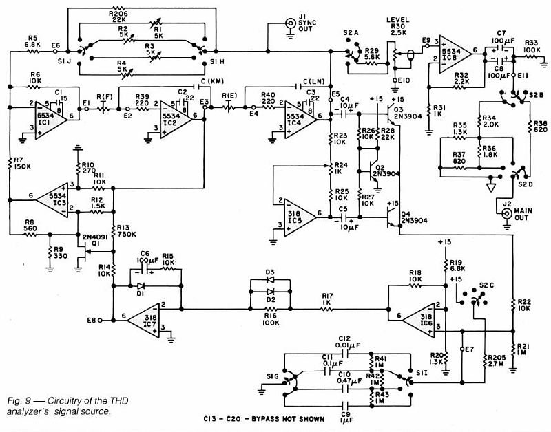
I decided to try a super-simple rectifier circuit I borrowed from Cordell.

Take a look around IC4, IC5 and Q2-Q3.

Image
Build A High Performance THD Analyzer Oscillator Cordell Audio June 1981.

It's really important that the modulating waveform not have any sharp hooks, corners or aberrations particularly as it comes out of baseline. Most opamp-based rectifiers have this because they run open loop at zero crossing. I've always thought Cordell chose this topology to reduce internal harmonics in his oscillator. Q2 pre-biases the transistors to linearize rectification.

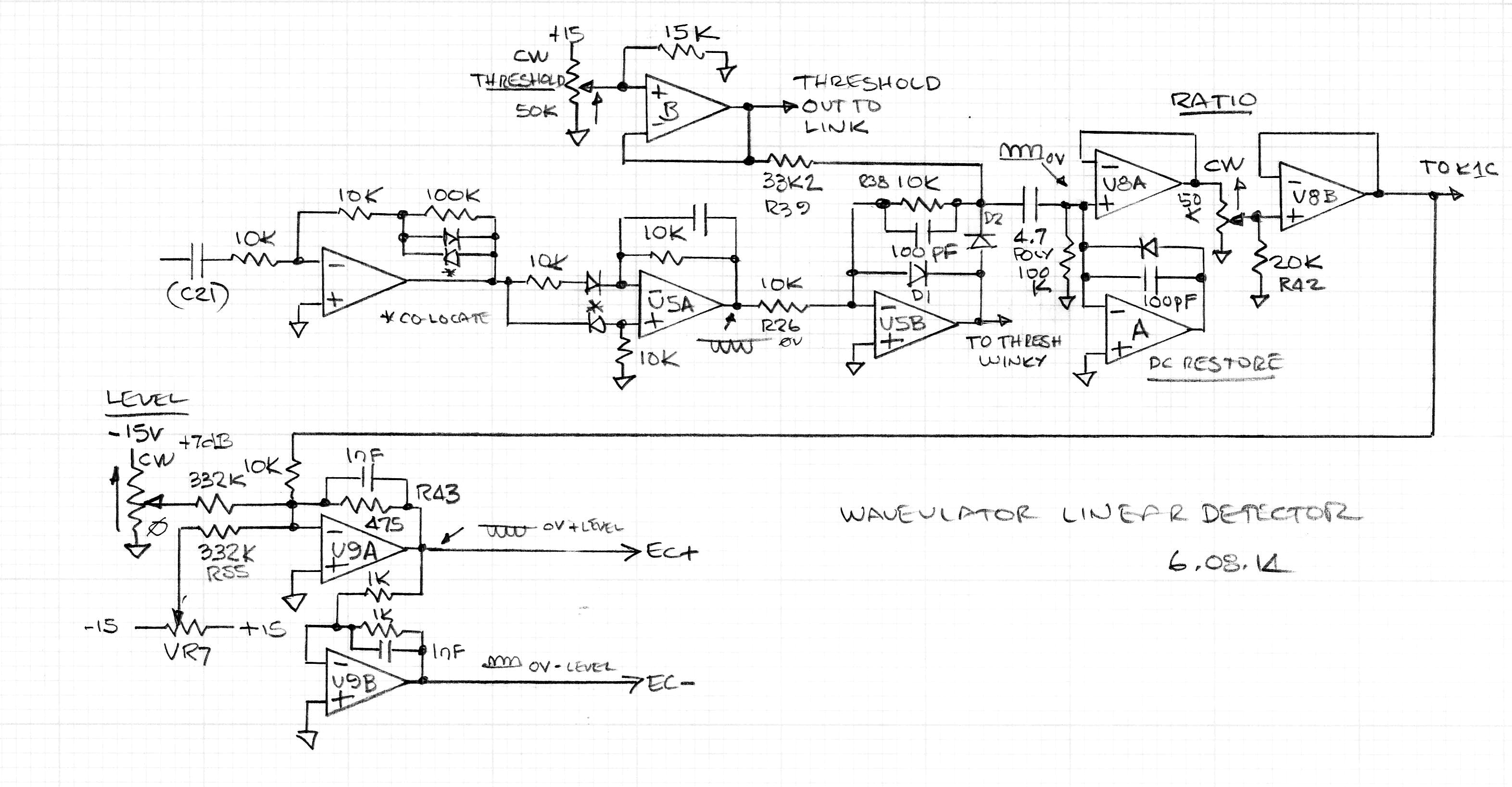
If you look at the linear rectifier in earlier posts (shown below) you'll see that the pre-distorter has a shunt resistor across the diodes. The absolute value stage that follows it doesn't have diodes within the feedback loop. The result is pretty clean rectification.

The threshold circuit that follows it does however. U5B has a pretty hefty compensation cap to provide rolloff and minimize hooks and sharp edges.

Image

The threshold circuit shown above clips out the lower portion of the modulating waveform and clamps it to the threshold voltage. The modulation however needs to have a 0V baseline so it has to be AC-coupled and DC-restored by the following stage at U8A.

I decided to try the Cordell circuit because it can be modified to provide the threshold function by biasing the rectifier off. Replacing Q2 with a variable voltage source sets the threshold voltage. An added advantage is that the output is referred to baseline so it does not require AC-coupling and DC-restoration.

Switching out of threshold is super clean.

The only disadvantage I see is that the transistor reverse B-E voltage limits the peak-to-peak input to around 8V. (4V peak). The threshold voltage ranges from about +550mV to -3.75V with a rectification range of about 100 mV p-p to 8V p-p. This can be worked around by scaling.

I'll post a circuit fragment soon but its basically IC4, IC5, Q2 and Q3 in the Cordell circuit with a couple of added op amp buffers for the Threshold voltage and output.
User avatar
mediatechnology
Posts: 5578
Joined: Sat Aug 11, 2007 2:34 pm
Location: Oak Cliff, Texas
Contact:

"Thresholded" Absolute Value Rectifier

Post by mediatechnology »

"Thresholded" Absolute Value Rectifier

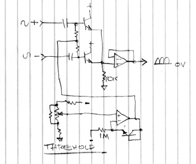
Some of my best projects begin life outside of my head as a lazy drawing with a Dixon Ticonderoga pencil and legal pad. Thinking about it more I might do well to regress and go back to using Crayons and a Big Chief pad. In order to continue the precedent I decided to sketch up the "Thresholded" rectifier I've been testing.

This rectifier, based on Cordell, works really well having super clean transitions out of the zero cross and threshold region even at 20 kHz.

Image
"Thresholded" Absolute Value Rectifier.

The two upper transistors are driven by out-of-polarity inputs. In the Cordell circuit the bases are biased up one Vbe for rectification at low levels.

When 0V is at the noninverting input of the lower op amp the bases of the rectifier transistors sit at +Vbe owing to the diode-connected transistor in the feedback loop and 1MΩ current sink.
The voltage on the non-inverting input goes more negative as the Threshold control is moved off its lower endstop.
This reduces the conduction angle of the rectifier by biasing the bases off so that only portions above the Threshold are passed to the output essentially lopping the bottom portion of the waveform off.
The output, used to ultimately modulate the VCA, is ground-referred without the need for AC-coupling and DC restoration.

This simpler circuit eliminates two op amps and has much cleaner switching coming out of the below threshold condition into providing modulation.
The HF performance is far better as well.
The only downside is that the input signal is limited to -3V peak to avoid the sum of the input and Vthreshold from exceeding the -6V minimum (typically -8V) reverse breakdown limit of the THAT300's base-emitter junction.
With the internal overload point being +21.5 dBu about 12 dB of attenuation is required to prevent detector overload.
Padding the detector input shouldn't be a problem though since it does not need to operate at super-low levels.

The next step is to find the best way to have even-order introduced.
There are a number of easy ways to do that.
Cordell has a trim to balance the upper and lower halves that could be used although it affects only the antipolarity level.
I'll also need the trim to adjust it but there may be a better way to introduce even-order by suppressing both polarities independently.
User avatar
mediatechnology
Posts: 5578
Joined: Sat Aug 11, 2007 2:34 pm
Location: Oak Cliff, Texas
Contact:

"Thresholded" Absolute Value Rectifier

Post by mediatechnology »

"Thresholded" Absolute Value Rectifier Oscillograms

Here are some oscillograms of the Thresholded Rectifier.

In all the images below turn-on and turn-off are very clean. There's no short-duration glitch during reverse recovery or slight tail one would get with a "closed-loop" rectifier using an op amp that goes open loop during zero cross. This is an "open loop" rectifier.

The first is 1 kHz with the Threshold set low so it appears like a traditional absolute value circuit. The vertical scale is 1V per division.

Image

At this setting the Waveulator would begin compressing immediately.

This is with a higher threshold that would set a break point about 1V below the peak value.

Image

In this image I used 20 kHz, set the threshold high and expanded the rectified 'scope trace to 200 mV per division so the portion of the waveform exiting and entering threshold can be seen.

Image

Its far cleaner than the linear and log detectors I used previously. The little glitches coming out of threshold, absent in these images, are audible.

We talk about those glitches here: viewtopic.php?p=6573#p6573
In this particular thread a biased diode rectifier is being evaluated and its typically better in this regard than conventional op-amp based absolute value circuits. Tubegeek, in a following post, figures out that my goal was to use this in a compressor. Brilliant.

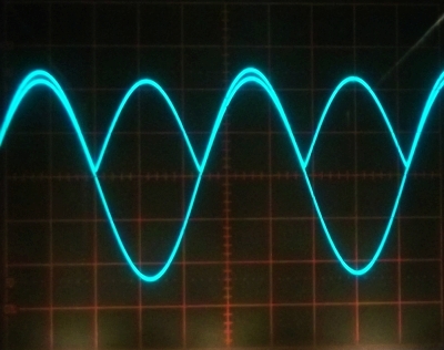
Update: I found an old 'scope photo of the Waveultor output that shows what glitches in the modulator sidechain do to the final result. It adds a raspy artifact about as bad as cross-over distortion.

Image
emrr
Posts: 585
Joined: Sun Mar 02, 2008 10:27 pm
Location: NC, USA
Contact:

Re: The Waveulator: Two VCA-based Clipper Saturators

Post by emrr »

Nice work
Best,

Doug Williams
Electromagnetic Radiation Recorders
TheeAldeen
Posts: 15
Joined: Wed Dec 28, 2022 11:10 pm

Re: The Waveulator: Two VCA-based Clipper Saturators

Post by TheeAldeen »

glad I am seeing this thread has blossomed since the waveulator page was sent to me - thanks

i would purchase for use a stereo linear unit for mix bus
*with whatever bells & whistles you all agreed on - I will keep my comments out of this discussion as they can get heavy & I am more than grateful to have ANY waveulator board available for purchase as I myself have still not learned pcb fabrication to be able to turn the schematics into anything other than a headache

I would also purchase for use an exaggerated version as stereo effect for my synth bus *currently the ka-width controller has sat in on this bus and has NOT-LEFT - it’s prototyped mess of wires still is as it original was the day I wired it up months ago & is used daily as it has been such a definitive module is sound design

lastly, I would purchase for use the guitar version


Wayne, thanks for sending me the waveulator thread & getting my head away from that 10-page 111c saturation slaughter of a thread — I promised myself I would 1. not make that same man’s mistake, & 2. Not contact you or purchase another ka module until I built the waveulator myself - finding this thread has grown since many months ago is a blessing & I’m grateful to be a spectator and watch it re-develop

jeffrey olson
User avatar
mediatechnology
Posts: 5578
Joined: Sat Aug 11, 2007 2:34 pm
Location: Oak Cliff, Texas
Contact:

Re: The Waveulator: Two VCA-based Clipper Saturators

Post by mediatechnology »

Thanks everyone for the encouragement.

The original Protoboard for this project was decommissioned several years ago. Now that I have a cleaner and simpler detector I'm more confident in moving forward. In the next few days I'll start building another Protoboard.
User avatar
mediatechnology
Posts: 5578
Joined: Sat Aug 11, 2007 2:34 pm
Location: Oak Cliff, Texas
Contact:

Re: The Waveulator: Two VCA-based Clipper Saturators

Post by mediatechnology »

Just a quick update to let everyone know that I'm building the Protoboard today and have the audio path finished.
On to the detector...
Post Reply