
With Hans Polak's help I recently redesigned the Flat Moving Coil Preamp PC board.
With highly-mismatched pairs the servo control point in the original design increased IM distortion because it varied collector current.
By moving the servo injection point to the emitters on the new board large mis-matches in transistor Vbe don't increase IM.
Simulation didn't match reality when, in the process of debugging, we found that passive component matching had a huge effect on the 1 kHz IMD produced by 19/20 kHz CCIF IM tests.
The 1 kHz IM, which is produced by even-order nonlinearities, is particularly pertinent for phono preamps because the RIAA curve magnifies the IM product, relative to the stimulus, by about +20 dB.
The following schematic shows the front-end which is fairly typical for most "Cohen" topologies.
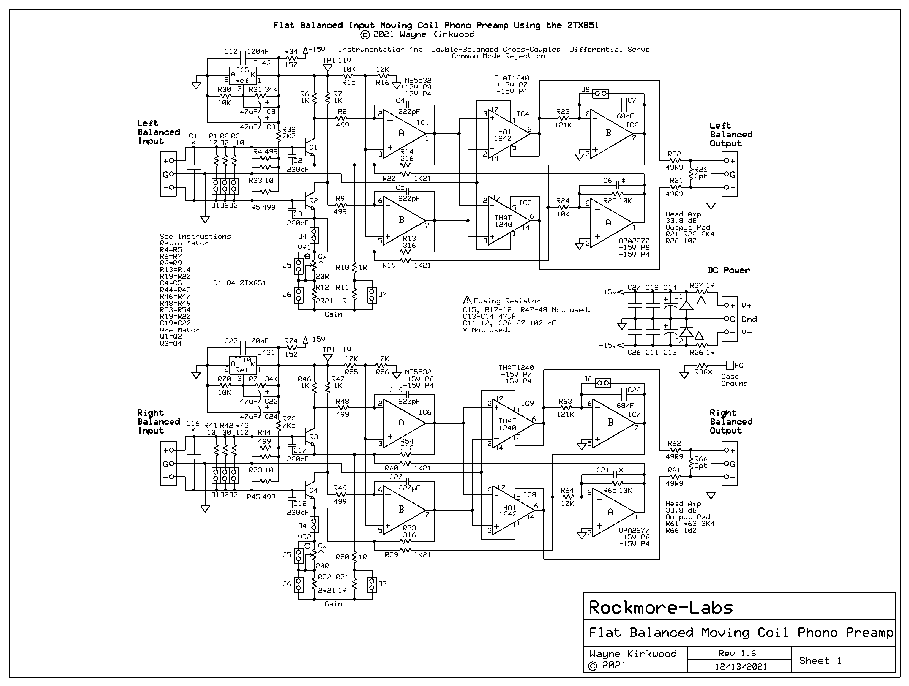
Schematic of the KA Electronics FMCP Flat Balanced Input Balanced Output Moving Coil Preamp Using the ZTX851
Large schematic: https://proaudiodesignforum.com/images/ ... amp_18.png
Even-order distortion in the "Cohen" front-end is attenuated by the common mode rejection stage formed by the cross-coupled THAT1240s.
Maintaining high common mode rejection is important not only for hum reduction but also even-order distortion reduction.
Cohen touched on component matching but didn't elaborate as to why.

Graeme, in Op Amp Applications, teaches us the importance of resistor matching to maintain high CMRR.
In the schematic for the Flat Moving Coil Preamp we see the following matched components.
R4 and R5, the input bias resistors, are matched to equalize source loading.
R6 and R7, the collector loads, R8 and R9, R13 and R14 which set gain, and R19 and R20 which inject servo all need to be ratio-matched as pairs to maintain CMRR.
The big surprise was the role of C4 and C5.
Their match is super-critical for HF common mode rejection and it was found they play a huge role in CCIF IM reduction.
When all of the aforementioned components are carefully matched the 1 kHz IM at 61.5 dB gain and +10 dBu output is at the A/D-D/A loopback level of around -120 dBc.
The following FFT is the result of resistors being matched to within 0.05% and capacitors to within 0.3%.
(Note that the spur to the right of 1 kHz is environmental.)

When C4 or C5 is mismatched by just 4.5% the IM increases by +20 dB to -100 dBc:

(R8 and R9, 499Ω, can be made 0Ω with many op amps without a decrease in stability but they provide the option to "tune" HF CMRR when C4 and C5 are not matched.)
All the preamps I build will now have super-matched resistors and compensation caps and I recommend it to anyone building a Cohen-style front end.
