Measuring the distortion of the DCAO2 Dual is a bit of a challenge because its low and I'm too cheap to buy an AP or DScope.
The following FFT illustrates the problem.
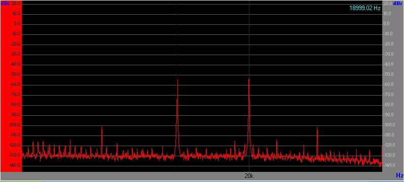
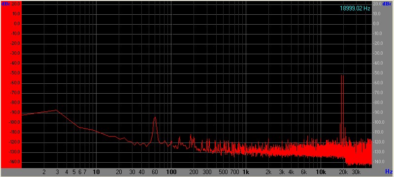
The green trace is the input residual and the red trace the output.
The distortion contribution at 750 mW into 30Ω
appears to measure only 0.0001% different.
It appears that the DCAO2 is actually subtracting the second harmonic.
Generator versus DCAO2 Distortion Signatures
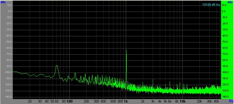
 Dual Class-A II DCAO2 1 kHz THD at 750 mW into 30Ω. Input is green, output is red.
Null testing, by subtracting the input fundamental and the generator residual distortion from the output, allows us to see far lower levels and measure the actual distortion contribution.
By driving the inverting "-" input of the Dual Class-A II balanced input its possible to passively subtract the input from the output and measure the difference in distortion.
Originally I used the other channel's line receiver to perform subtraction which works equally well at 1 kHz but doesn't allow capacitive trimming to increase the HF null.
Dual Class-A II DCAO2 1 kHz THD at 750 mW into 30Ω. Input is green, output is red.
Null testing, by subtracting the input fundamental and the generator residual distortion from the output, allows us to see far lower levels and measure the actual distortion contribution.
By driving the inverting "-" input of the Dual Class-A II balanced input its possible to passively subtract the input from the output and measure the difference in distortion.
Originally I used the other channel's line receiver to perform subtraction which works equally well at 1 kHz but doesn't allow capacitive trimming to increase the HF null.
The null depth is adjustable by using the DCOA2's input trim.
Phase shift at frequency extremes limit the available null depth.
At 10 kHz the phase shift is still relatively low and can be compensated by a low value capacitor in parallel with one leg of the resistive "subtractor."
At the 20 Hz extreme the DCAO2's coupling capacitor requires bypassing to obtain a reasonable null.
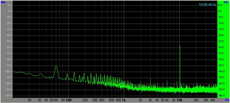
This FFT is the nulled subtracted output showing the residual distortion:
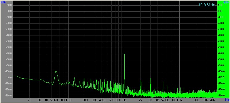 Dual Class-A II DCAO2 1 kHz THD at 750 mW into 30Ω. Null test. Output minus input.
The 1 kHz fundamental and generator distortion are nulled by approximately 70 dB.
Since the generator's distortion is in the -70 to -90 dB range and then rejected by 70 dB it's distortion is in the noise floor.
The remaining harmonics are those contributed by the DCAO2.
Once the fundamental and harmonics are nulled by 20-30 dB their contribution to the measured distortion is small.
When the fundamental is sufficiently low, the measured distortion products do not change appreciably with additional null depth.
The resistive summing network (1K) has a 6 dB loss.
To compensate for the network loss the measurement scale is adjusted upward by 6 dB to match the output reference level.
The second harmonic in the FFT above is very small, about -112 dB from the fundamental.
The third sits at about -110 dB; the fifth about -115 dB.
The power sum of the first four harmonics is -107 dB, 4.5 ppm or 0.00045%.
The 1 kHz THD of the DCAO2 is 0.00045% at 750 mW.
At 10 kHz 750 mW into 30Ω distortion rises as expected because there's lower open loop gain.
 Dual Class-A II DCAO2 10 kHz THD at 750 mW into 30Ω. Null test. Output minus input.
The third harmonic of 10 kHz is at -93 dB; the second at -113 dB.
The power sum of H2 and H3 are about -92.9 dB which is 22.6 ppm or 0.00226% THD.
At 100 mW power levels null testing finds the THD needle in the haystack.
DCAO2 10kHz FFT at 100 mW into 30Ω:
 Dual Class-A II DCAO2 10 kHz THD at 100 mW into 30Ω. Null test. Output minus input.
The third harmonic is not observed. H2 is about -118 dB or 1.3 ppm.
THD at 10 kHz 100 mW into 30 Ω is approximately 0.00013%.
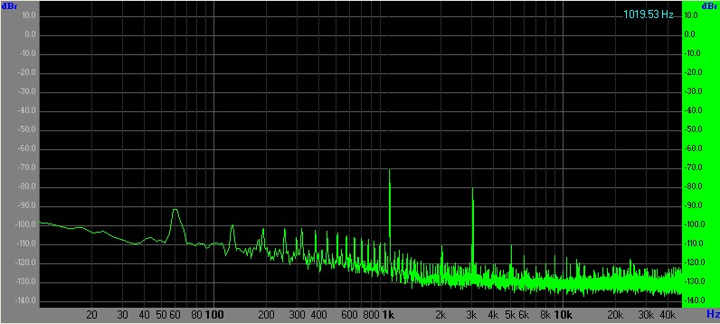
DCAO2 1kHz FFT at 100 mW into 30Ω:
 Dual Class-A II DCAO2 1 kHz THD at 100 mW into 30Ω. Null test. Output minus input.
The third harmonic is a blip at about -110 dB. H2 is about -115 dB. The power sum is -109 dB or 3.5 ppm
THD at 10 kHz 100 mW into 30 Ω is approximately 0.00035%
DCAO2 Dual Class-A II Distortion at 100 mW into 30Ω with the output running open loop:
DCAO2 1 kHz 100mw Open Loop Output
 Dual Class-A II DCAO2 1 kHz THD at 100 mW into 30Ω with the output running open loop. Null test. Output minus input.
DCAO2 10 kHz 100mw Open Loop Output
Dual Class-A II DCAO2 1 kHz THD at 100 mW into 30Ω with the output running open loop. Null test. Output minus input.
DCAO2 10 kHz 100mw Open Loop Output
 Dual Class-A II DCAO2 10 kHz THD at 100 mW into 30Ω with the output running open loop. Null test. Output minus input.
In the 10 kHz FFT above a small capacitor was placed in one leg of the summing point to compensate for phase shift and further reduce the null point.
The reduced null depth has no effect on the measured harmonic levels.
The DCAO2 third harmonic distortion at both 1 and 10 kHz with the output open loop is around -79 dB, 112 ppm, or 0.0112%. (100 mW 30Ω load.)
Conclusion
The 100 mW 1 kHz closed loop versus open loop numbers are 0.00035% versus 0.0112%.
At 750 mW 1 kHz closed loop the distortion is 0.00045%.
There is a big difference in closed loop versus open loop output impedance at 40 mΩ (at 20 kHz it's still only 70 mΩ) versus 2Ω open loop.